From the new textbook Telecom 101 Fifth Edition: 2020

Figure 111. SFP Optical Transceivers
10.5 Optical Ethernet
Optical Ethernet is signaling MAC frames (Section 4.4) from one device to another by flashing a light on and off; light on represents a 1 and light off represents a 0 in many systems.
The light, called a wavelength or lamda – λ in Greek – is as close to one single pure frequency as possible, in the infra-red, lower frequencies than what our eyes detect.
In sophisticated systems, the wavelength might be modulated with QAM (Section 3.4) to increase the bit rate.
Normally, Optical Ethernet is implemented as point-to-point connections: from a hardware port on one switch or router to a hardware port on another switch or router in a different building. This includes connections between core routers in cities, connections between routers and switches within a city, and connections from carriers to customers.
10.5.1 SFP Modules and Connectors
The light is generated by a laser controlled by pulses of electricity at the transmitter. The intensity and sometimes phase of the light is modulated, i.e. changed in discrete steps, to represent bits optically based on the pulses of electricity. Up to 80 km (50 miles) away at the other end of a tube of glass thinner than one of your hairs, a photodetector at the receiver measures the received light and decides what bits are being represented, and transmits them onward as pulses of electricity.
As illustrated in Figure 111, most systems use two fibers, one for each direction. A device combining the transmitter and detector functions is called an optical transceiver.
This device has metal connectors on one side to plug into a slot on a router or switch, and optical connectors on the other side, either factory- or field-installed on the fibers plugged into the transceiver.
These transceivers are typically implemented as Small Form-factor Pluggable (SFP) modules, which are hot-swappable in the terminating equipment at each end.
100 Gb/s being communicated through this transceiver is the high end of commercially-deployed technology in 2020.
In some cases, the SFP modules are embedded in the terminating equipment, meaning the fibers are plugged into the terminating equipment. This allows re-use of existing fiber. In other cases, the SFP modules are attached to fiber cables by the fiber cable manufacturer, meaning the SFP module is plugged into the terminating equipment. This ensures the fiber and transceiver technology are matched and the optical connection is a high-quality “factory” connection.
The SFP module format is not the subject of a standard, but rather described in industry Multiple Sourcing Agreements (MSA).
10.5.3 IEEE Standards
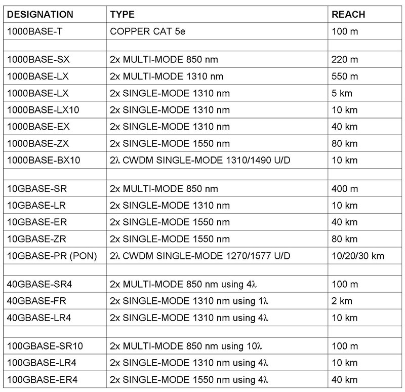
There are many technologies for transceivers implemented in the SFP module. Some are proprietary; many are standardized by the IEEE. In practice, the same manufacturer’s product is used at both ends of the fiber to ensure compatibility. The table in Figure 112 lists current IEEE standards. More will be published in the future.

Figure 112. IEEE Optical Ethernet Standards
Most technologies use one fiber for each direction. Some, like for fiber to the home, use two wavelengths for two directions on one fiber. The bitrate of the standards beginning with 1000 is 1,000 Mb/s, or 1 Gb/s. A G at the beginning means Gigabits/second. 40 and 100 Gb/s technologies split the bitstream into subrates and transmit them in parallel on different wavelengths called paths or lanes.
The reach is the maximum length of fiber between devices. Single-mode and multimode are designations for different qualities of fiber. Most if not all builds today use single-mode fiber.
Source: Telecom 101 textbook / reference book, Fifth Edition: 2020 available in print and eBook.
