This lesson is an introduction to network access technologies, called the “last mile”, the physical connection between the user and the network; the face of the telecom network to users.
We group access technologies by physical medium: copper, fiber and wireless, then survey the main technologies in each area.
Subsequent courses and lessons drill deeper into the technologies. This lesson is part of the introduction.
Copper includes twisted pair loops, LAN cables and old-fashioned T1s, as well as coaxial cable CATV infrastructure.
Fiber means Optical Ethernet, shared links for residences via Passive Optical Networks and dedicated links for businesses.
Wireless includes 4G LTE and 5G, used for both fixed and mobile applications, and satellites.
Optical Ethernet is signaling MAC frames
(Section 4.4) from one device to another by flashing a light on and off; light
on represents a 1 and light off represents a 0 in many systems.
The light, called a wavelength or lamda – λ
in Greek – is as close to one single pure frequency as possible, in the
infra-red, lower frequencies than what our eyes detect.
In sophisticated systems, the wavelength
might be modulated with QAM (Section 3.4) to increase the bit rate.
Normally, Optical Ethernet is implemented as
point-to-point connections: from a hardware port on one switch or router to a
hardware port on another switch or router in a different building. This
includes connections between core routers in cities, connections between
routers and switches within a city, and connections from carriers to customers.
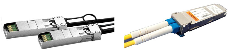
10.5.1 SFP Modules and Connectors
The light is generated by a laser controlled
by pulses of electricity at the transmitter. The intensity and sometimes
phase of the light is modulated, i.e. changed in discrete steps, to represent
bits optically based on the pulses of electricity. Up to 80 km (50 miles) away
at the other end of a tube of glass thinner than one of your hairs, a
photodetector at the receiver measures the received light and decides what bits
are being represented, and transmits them onward as pulses of electricity.
As illustrated in Figure 111, most systems
use two fibers, one for each direction. A device combining the transmitter and
detector functions is called an optical transceiver.
This device has metal connectors on one side
to plug into a slot on a router or switch, and optical connectors on the other
side, either factory- or field-installed on the fibers plugged into the
transceiver.
These transceivers are typically implemented
as Small Form-factor Pluggable (SFP) modules, which are hot-swappable in the
terminating equipment at each end.
100 Gb/s being communicated through this
transceiver is the high end of commercially-deployed technology in 2020.
In some cases, the SFP modules are embedded
in the terminating equipment, meaning the fibers are plugged into the
terminating equipment. This allows re-use of existing fiber. In other cases,
the SFP modules are attached to fiber cables by the fiber cable manufacturer,
meaning the SFP module is plugged into the terminating equipment. This ensures
the fiber and transceiver technology are matched and the optical connection is
a high-quality “factory” connection.
The SFP module format is not the subject of a
standard, but rather described in industry Multiple Sourcing Agreements (MSA).
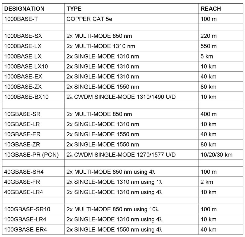
10.5.3 IEEE Standards
There are many technologies for transceivers
implemented in the SFP module. Some are proprietary; many are standardized by
the IEEE. In practice, the same manufacturer’s product is used at both ends of
the fiber to ensure compatibility. The table in Figure 112 lists current IEEE
standards. More will be published in the future.
Figure
112. IEEE Optical Ethernet Standards
Most technologies use one fiber for each
direction. Some, like for fiber to the home, use two wavelengths for two
directions on one fiber. The bitrate of the standards beginning with 1000 is
1,000 Mb/s, or 1 Gb/s. A G at the beginning means Gigabits/second. 40 and
100 Gb/s technologies split the bitstream into subrates and transmit them in
parallel on different wavelengths called paths or lanes.
The reach is the maximum length of
fiber between devices. Single-mode and multimode are designations for
different qualities of fiber. Most if not all builds today use
single-mode fiber.
Young man illustrating Bluetooth channel as frequency-hopping pattern using a pogo stick. Click the image to watch the full lesson. The text that follows is from the course book.
Bluetooth is a set of standards for short-range digital radio communication published by a consortium of companies called the Special Interest Group. It was originally developed as a wireless link to replace cables connecting computers and communications equipment.
Bluetooth connections are called piconets and Personal Area Networks since (in theory) up to eight devices can communicate on a channel within a range of 1 to 100 meters depending on the power.
In reality, Bluetooth is mostly used point-to-point with ten meters range.
The first data rate for Bluetooth was 0.7 Mb/s, followed by an enhancement to “3” Mb/s (2.1 Mb/s in practice). A High Speed variation employs collocated Wi-Fi for short high-bitrate transmissions at 24 Mb/s. The Smart or Low Energy variation allows coin-sized batteries on devices like heart-rate monitors.
Bluetooth applications
Applications include wireless keyboard, mouse and modem connections… though today, 2 Mb/s Bluetooth is likely slower than the modem.
Bluetooth is used to replace wires connecting a phone to an earpiece, or to an automobile sound system for hands-free phone calls while driving. In this case, both two-way audio and two-way control messages are transmitted.
Bluetooth is also used to stream music from a smartphone to a receiver connected to an amplifier and speakers in an automobile or in a living room.
In the future, wireless collection of readings from devices like heart-rate monitors will be widespread.
Each of these types of applications corresponds to a Bluetooth profile, which is a specified set of capabilities and protocols the devices must support.
Bluetooth implements frequency-hopping, where the devices communicate at one of 79 carriers spaced at 1 MHz in the 2.4 GHz unlicensed band for 625 microseconds (µs), then hop to a different carrier for 625 µs, then to another, in a repeating pattern known to both devices. A particular hop sequence is called a channel, and is identified by an access code.
This is called Frequency-Hopping Spread Spectrum (FHSS), since hopping between 79 carriers spreads energy across spectrum 79 times wider than one carrier. It has the advantage of reduced sensitivity to noise or fading at any particular carrier.
If different pairs of devices are using different hop sequences, they can communicate at the same time in the same place without interfering. There are security advantages if the hop sequence can not be determined by a third party.
The initiator of communications is called the master. It determines the frequency hopping pattern, when the pattern begins, when a packet begins and when a bit begins. The packet and bit timing is based on the master’s clock, which ticks every 312.5 microseconds. Two ticks make a slot. A slot corresponds to a hop. The master transmits and the slave listens in even-numbered slots; vice-versa in odd-numbered slots.
To establish the channel, the master derives a channel access code from its Bluetooth address, and indicates the code to the slave at the beginning of every packet. Both master and slave use this to determine the actual frequency-hopping sequence.
Data is organized into Bluetooth packets for transmission. Packets can be 1, 3 or 5 slots long. A bit rate of 2 Mb/s would mean Bluetooth packets are about 150, 450 or 750 bytes long.
Discovering other devices means sending requests in packets on pre-defined channels called inquiry scan channels. Making a device discoverable means it listens on the inquiry channels, and responds to inquiries with information like its Bluetooth address, name and capabilities. This results in a list of Bluetooth devices displayed on the discovering device, such as a smartphone.
Connecting to a device means paging the device on its paging channel, a channel with access code derived from the target’s Bluetooth address. Devices listen on their paging channel, and respond to pages to establish a session. Once the session setup protocol is completed on the paging channel, the devices begin communicating on the channel defined by the master.
The frequency hopping pattern can be adapted to skip carriers where the signal to noise ratio is permanently low, to improve overall performance.
I hope you’ve enjoyed this tutorial!
This discussion is covered in the following Teracom training courses:
• DVD-Video Course V6: Understanding Wireless
https://www.teracomtraining.com/video_courses.htm