Tutorial: Voice Digitization (1)

Last month’s Google Analytics report said a top-three trending page on the teracomtraining.com site was the tutorial on voice digitization.

The material in that tutorial, graphics and text, was created in 1999 for a course workbook. But the fundamentals rarely change, and it is just as relevant and accurate today as it was then. Who are we to argue? Here it is again:

– – –

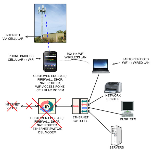
We look in detail at the voice digitization process to derive the data rate – number of bits per second – required to communicate a digitized voice signal, and understand the steps involved. Once the voice – half of a phone call – is digitized, it can be segmented and carried in IP packets along with everything else in the modern broadband converged IP telecommunications network.

There are three steps in voice digitization: quantization, sampling and coding.

Quantization: Change from continuous in value to discrete in value

Sampling: Change from continuous in time to discrete in time

Coding: Code value of sample into standard-format 1s and 0s

Voice Digitization (1)

Voice Digitization: Quantization, Sampling and Coding

continuous signal is one that exists at all values.  Pick any two values, and there can always be a value between them… like the voltage on copper wires representing your voice when making a phone call.  

discrete signal is one that is defined only at specific values, and is not defined between… like the number of people in a room.

Quantization is the process of changing from a signal that is continuous in value to a signal that is discrete in value. This is accomplished by dividing the possible range of values into a number of bins or levels or steps, and assigning a number to each of these levels.

Later, when asked what the value of the signal is, we say that the signal is “in level #4” rather than quoting its voltage accurate to some number of decimal places.  

Another example of quantization is sugar cubes. Instead of putting some random fractional value of a teaspoon of sugar in your coffee, your choices are “one lump or two”. The sugar has been quantized into uniform increments.

Many hardware chips implement 16-bit quantization, meaning 65,536 levels. These are consolidated into a smaller number of levels by software during the coding step below.

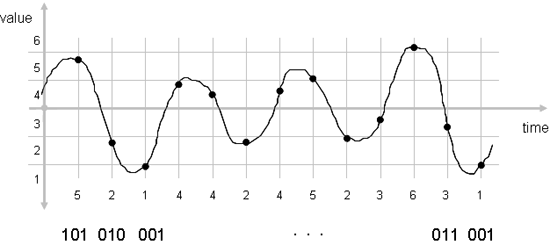
Sampling is the process of changing the signal from being continuous in time to one that is discrete in time: on a regular basis, we measure the value of the signal and record it. The value of the signal is recorded as the quantization bin number it was in.

How often do we need to sample the signal? A mathematician by the name of Nyquist proved that the signal has to be sampled more than twice as often as the frequency bandwidth of the signal to be able to reproduce it. This is called the Nyquist Rule.

The final step is coding. The value of the signal taken at each sample (the level number) must be coded into 1s and 0s so that it can be efficiently transmitted or stored in a computer.  

We are interested in using standard coding methods like G.711 for landlines or the AMR codec used for cellular, so that any device or software app can decode the value at the far end.  Skype uses a proprietary coding method, meaning that only the Skype app can be used to decode the values at the far end; whatsapp, for example, is not compatible.

The codes representing the value of the samples are then transmitted to the far end.

At the far end, the reverse process is performed: re-creating the analog waveform from the received codes by de-coding the level number, generating a voltage with a value equal to that of the center of the level, and smoothly changing the voltage in this manner as each new code comes down the line.

The objective of doing all of this is to move the analog voice signal from the near end microphone to the far end speaker, without adding in any noise.

Bonus: the digitized voice can be carried in IP packets interspersed with video, data and Internet traffic, on the modern broadband converged IP network.

There is in fact a small amount of noise added in, up front, as part of the analog-to-digital conversion. This is the quantization error, the difference in value between the center of the level, and where the signal actually was.

How do we make the quantization error smaller on average? Make the levels finer. How many levels does the telephone company use? Enough so that a human can’t hear the quantization error noise on the line. Read the exciting conclusion in

NEXT TUTORIAL:  Voice Digitization 2

ALL TUTORIALS

Tutorial: Network Core Nodes

Section 10.6.4 of Telecom 101: Sixth Edition 2022

A carrier’s network core, colloquially referred to as their backbone, provides high-capacity, high-availability connections, notionally between cities.

The connections can be between Central Offices, wire centers, toll centers, other switching centers, CATV head ends, Mobile Telephone Switching Offices, Internet Exchanges and/or data centers.

Fiber optics is used as the basis of the connections since it can support very high numbers of bits per second. Lower-speed (and lower-cost) circuits are used to provide access to this core to users.

FIGURE 121 NETWORK CORE NODE

At the end of each fiber that makes up the network core is a router. The router is sometimes called a network node, after the French word for knot. In some cases, the entire building housing this router is called a node.

A knot, because in addition to connecting core fibers to other cities, the many local access fibers to buildings, neighborhoods, cell sites and everything else are also connected to the core at this node.

Figure 121 provides a closer look at the architecture of a core network node.

DWDM (Section 10.4) is used on core fibers to increase the capacity connecting routers in different cities to bit rates measured in the Terabits per second.

A gateway router is placed as a point of traffic control between access circuits on the right and the core router on the left. This gateway router also implements MPLS (Chapter 17), which is used to manage capacity on the network circuits.

Terminating a physical fiber means plugging it into an Optical Ethernet SFP transceiver inserted in a hardware port in a rack-mount device.

Routers are built with a relatively small number of hardware ports between which they can relay packets at line speed. Some of these ports would terminate core fibers, and others terminate connections to aggregation devices for access fibers via that node’s gateway router as illustrated in Figure 121.

Layer 2 switches (Section 15.4) with up to hundreds of Optical Ethernet hardware ports each are used to terminate the access fibers, which can number in the thousands.

Layer 2 switches are also data concentration or aggregation devices, interspersing traffic from all of the access circuits into high-speed streams to feed to the router. Everything works in both directions at the same time.

Layer 2 switches also implement VLANs (Section 15.5), a critical tool for segregating different users on the same access fibers in cooperation with additional Layer 2 switches connected downstream, as described in the next section.

– – –

This is one small piece of Telecom 101.

Join thousands of satisfied customers, and get the entire book today!

Tutorial: Wireless Spectrum and Radio Bands

Lesson 3 of CWA Course 2231 Wireless Fundamentals
20 minutes running time.

Every country has the sovereign right to manage energy at radio frequencies in its territory. When the airspace through which the radio waves travel is public property (which is most of the time), and there is contention for its use (which is all of the time), regulation is required to allow the rational use of the shared resource.


The range of radio frequencies, called the radio spectrum, is divided into blocks of frequencies allocated for different services. Allocations are divided into allotments, which are bands of frequencies assigned to specific users or to the public. A license to emit radio-frequency energy at the specified frequencies in a specified area is issued by government to record the assignment of the allotment and the conditions for its use.

… these lesson notes continue on page 19 of the CWA Study Guide.

Tutorial: Mobile Operators, MVNOs and Roaming

Extracted from Chapter 9 of the Telecom 101 reference book.
Note: acronyms and abbreviations used below are explained in lessons leading up to this one.

9.7 Mobile Operators, MVNOs and Roaming

9.7.1 Mobile Network Operator

Mobile Network Operator (MNO) is the term usually used to refer to a facilities-based carrier, i.e. a company that owns base stations, a mobile switch, backhaul between them, and spectrum licenses, and sells services to the public… and to other carriers.

The MNO implements external links to other carriers for PSTN phone calls and for Internet traffic.

For PSTN phone calls, the MNO implements a fiber optic connection to a building traditionally called a Toll Center or Class 4 switching office. The termination of their fiber in that building is called a POP. It is their physical point of presence in the building.

Many other carriers have POPs in the building, including the ILEC, IXCs, CATV companies, other mobile carriers, and any other company that wants to connect phone calls to a phone on the MNO’s network.

The operator of the toll center, usually the ILEC, provides a switch in the Toll Center to switch phone calls from one carrier’s POP to a different carrier’s POP.

For Internet access, the MNO implements a fiber optic connection to one or more Internet Exchange buildings, where they pay the operator of the IX to route packets to other carriers with whom the MNO has established IP packet transit and peering arrangements.

9.7.2 Mobile Virtual Network Operator

Mobile Virtual Network Operator (MVNO) is the term used to refer to a non-facilities-based carrier… one that does not own the hardware or spectrum licenses or POPs.

Instead, the MVNO enters into a long-term contract with one or more facilities-based carriers to have them supply a “white label” service that the MVNO sells.

Typically the MVNO will develop a unique branding and sell smartphones and tablets to go along with its service.

When the MVNO deals exclusively with one carrier, the MVNO bill to the customer would be typically generated by the facilities-based carrier as a white-label service.

If the MVNO is very large and deals with multiple carriers, the MVNO may operate their own billing system, which is a significant investment.

The facilities-based carrier charges to the MVNO includes a volume-discount rate for IP addresses and Internet traffic, voice-minute airtime and switched access to the POP for PSTN phone calls.

The MVNO also has to pay for connectivity from the POP to other toll centers for “long-distance” connections, and the switched-access charge at the far end.

The rate plan the MVNO pays could be a mix of fixed-rate leases and usage-based billing.

Unless the MNO is obliged to sell capacity to MVNOs through regulations and tariffs, the nature of the plan is confidential business information.

9.7.3 Roaming

Roaming service is very similar to the service provided to MVNOs, in that it is the MNO that is providing the airlink, base stations, backhaul, mobile switch and connections to the PSTN and Internet.

In the case of roaming, the visitor uses their own phone, and billing is usage-based.

Roaming is an important feature for smaller players: they are facilities-based in selected cities, but to offer a national and international service to their customers, they must have roaming agreements in place with MNOs in other locations.

By denying roaming service to smaller or startup carriers, or charging an exorbitant price for roaming, an incumbent carrier can erect a barrier against competition.

In many countries, the right to roam and the wholesale cost of roaming is regulated to encourage competition.


These topics are covered in:

Free Lesson : Network Address Translation

Free Lesson!
Course 2213 – IP Addresses, Packets and Routers
Lesson 9: Network Address Translation (NAT)

This lesson explains the standard practice of assigning private IP addresses to machines inside the building, and getting a single public IP address from the ISP providing the Internet access. Everyone in the building shares the single public IP address via Network Address Translation. This lesson explains how NAT works.

This free online network training course lesson is in both the CTNS Certification Package and the CTA Certification Package.

Click here to watch for free now!

Course 2213 IP Networks, Routers and Addresses

IP Addresses • Packets • Networks • Routers • Static and Dynamic Addresses • DHCP • Public and Private Addresses • NAT • IPv6

IP Networks, Routers and Addresses is a comprehensive course on IP networking fundamentals: IP packets, IP addressing and IP routers.

We’ll see how routers implement the network with packet-switching, that is, relaying packets from one circuit to another, and how routers are a point of control for network security. We’ll introduce the term Customer Edge (CE), and understand the basic structure and content of a routing table.

Then we’ll cover the many aspects of IP addressing: IPv4 address classes, dotted decimal, static vs. dynamic addresses, DHCP, public vs. private addresses, Network Address Translation, and finish with an overview of IPv6.

Course Lessons
1. Introduction
2. Review: Channelized Time-Division Multiplexing (TDM)
3. Statistical Time-Division Multiplexing: Bandwidth-on-Demand
4. Network: Bandwidth on Demand + Routing
5. Routers
6. IPv4 Addresses
7. DHCP
8. Public and Private IPv4 Addresses
9. Network Address Translation
10. IPv6 Overview
11. IPv6 Address Allocations and Assignment

Based on Teracom’s famous Course 101, tuned and refined over the course of 20 years of instructor-led training, we’ll cut through the jargon to clearly explain IP and routers, packets and addresses, the underlying ideas, and how it all works together… in plain English.

Press 1 to understand how modems work

Mini-Tutorial: Press 1 to understand how modems work

This is a recording of a call to a number with an Interactive Voice Response (IVR) behind it.  You call this number to learn how modems work.

Listen to the audio.

Although the caller presses the wrong button, it nonetheless reveals how modems work: using tones to communicate the binary numbers 1 and 0. 

Tutorial – The Last Mile: Copper, Fiber and Wireless

Lesson 7 The Last Mile: Copper, Fiber and Wireless from the new course Introduction to Broadband Converged IP Telecom. 
Here’s the full lesson free, in full quality, with our compliments.

The Last Mile lesson link

This lesson is an introduction to network access technologies, called the “last mile”, the physical connection between the user and the network; the face of the telecom network to users.

We group access technologies by physical medium: copper, fiber and wireless, then survey the main technologies in each area.

Subsequent courses and lessons drill deeper into the technologies. This lesson is part of the introduction.

Copper includes twisted pair loops, LAN cables and old-fashioned T1s, as well as coaxial cable CATV infrastructure.

Fiber means Optical Ethernet, shared links for residences via Passive Optical Networks and dedicated links for businesses.

Wireless includes 4G LTE and 5G, used for both fixed and mobile applications, and satellites.

Get more Info

Tutorial – What Modems Do: Carrier Frequencies, Phase Shifts and QAM

Modulation means producing energy that is vibrating at a single pure frequency, called a carrier frequency or subcarrier, and changing aspects of it in discrete steps to represent bits. 

The device that performs this function is called a modulator.  A demodulator is required at the far end to interpret the carrier frequency and decide what bits it is representing at any given time.  Clearly, we want devices to do both functions to implement two-way communications, so they are called modulator/demodulators or modems for short.

One aspect of the carrier than can be changed to represent bits is the volume or amplitude of the carrier: changing the amplitude of the carrier in discrete steps makes changes that represent bits.

Another aspect is the phase of the carrier: when the peak of the cycle is happening, in time, with respect to other carriers. Changing the time of the peak so it happens a bit earlier than others, or making it happen a bit later is making changes to the phase of the carrier that can represent bits (Figure 29).

Combinations of phase and amplitude shifting is called Quadrature Amplitude Modulation (QAM). QAM-64 means 64 possible different combinations of 8 different phases and 8 different amplitudes.

Each combination, also called a symbol or signal, is assigned a number. Binary numbers 6 bits long are required to give binary numbers to each of the 64 combinations.

7.3.2 Communicating Six Bits: Sending One of 64 QAM Signals

To communicate six bits in one fell swoop on a carrier, the transmitter generates electricity vibrating at the carrier frequency with the phase and amplitude corresponding to the combination indicated by the six-bit number.

The electricity is communicated on coaxial cables to Cable modems, on twisted pair to DSL modems, turned into radio by antennas for communication through space, or turned into light for communication in tubes of glass in very high capacity fiber transmission systems.

When the receiver detects energy at that single pure carrier frequency, it measures the phase and amplitude, and once it has decided, spits out the six-bit number of the combination it is hearing, and Bob’s your uncle.

7.3.3 Baud Rate

To get many bits per second, the procedure has to be repeated often!

Repeating it once per second yields 6 bits per second; the combination of phase and amplitude of the carrier is maintained for one second then changed to a different combination representing the next six bits.

The rate at which the procedure is repeated is called the baud rate, signaling rate and symbol rate.

The baud rate, how often a new combination can be applied to the carrier to communicate another 6 bits, is limited by interference called harmonics, where energy gets spread into adjacent frequencies, and interferes with communications on other carriers.

7.3.4 Orthogonal Frequency Division Multiplexing (OFDM)

When there are multiple carriers (called subcarriers) each running a modem, and the baud rate is the same as the subcarrier spacing, the harmonics from all subcarriers cancel out.

Eliminating this source of interference allows successful data transmission in parallel on closely spaced subcarriers.

This is a prime design characteristic of Orthogonal Frequency Division Multiplexing (OFDM), used on LTE, 5G, Wi-Fi, cable modems and DSL, and is the sweet spot for baud rate in terms of efficiency.

Source: CTNS Study Guide 2021, Course 2206, Section 7.3

Tutorial: How to Use Cellular as Backup Internet Access When Your DSL, Cable or Fiber Internet Dies

The Internet connection at your office dies. Lights on your modem are flashing in a strange pattern. You call the ISP, and they quickly diagnose that the modem power supply has failed, and they will overnight you a replacement. Presumably you are not the first person to have this problem with that modem.

So how do you continue to operate while you are waiting for the replacement power supply? It’s hard to run your business without e-mail and ordering and administration systems, which are all accessed via the Internet.

If you want availability, you need two connections to the Internet, so if one fails you are not out of business. We go over this in the lesson “Mature Competitive Carrier Network: Regional Rings, POPs and MANs”, slide 3.17 of Course 101, Telecom Datacom and Networking for Non-Engineers, and mention it in pretty much every other course.

A large business will be a station on a Metropolitan Area Network, which is a ring, meaning two connections to the Internet for that business and automatic reconfiguration in the case of one failing. But this is expensive… the second connection is not free.

Small and medium businesses usually have a single DSL or cable modem connection to the Internet. When that fails, connectivity to email, ordering and administration servers is impossible, and many businesses these days would be “dead in the water” until the ISP fixes the problem with their hardware.

Unless you have an Android smartphone, a good “data” plan and a laptop with WiFi running Windows.

The scenario described happened at our office last week. Since many of our customers might find themselves in a similar situation – even at home – I thought I’d share the quick and painless solution I came up with. Even if you’re not likely to need this solution, understanding how it works will no doubt sharpen your understanding of the devices involved and their functions.

In this tutorial, I will use the technology in our office: 50 Mb/s DSL, Android smartphone and Windows laptop. The solution is equally applicable to an Internet connection using a cable modem or if you are one of the lucky few, an Internet connection via fiber.

For the smartphone and laptop, there may be equivalent functions on Apple products, but as I am allergic to Apples, we don’t have any in the office. I’m posting this tutorial on our our Facebook page, our GoogleMyBusiness page, or our blog; I invite someone better able to tolerate Apple products to leave a comment whether and how the iPhone and MacBook can perform the required functions.

normal office lan and wired internet connection

The diagram above illustrates the normal network setup in our office, a typical configuration for networking at a small or medium business. On the left is the access circuit to the Internet Service Provider (ISP), terminating on a modem in our office.

The modem is contained in a box that also includes a computer and an Ethernet switch. This box is more properly called the Customer Edge (CE). The computer in the CE runs many different computer programs performing various functions: Stateful Packet Inspection firewall, DHCP server offering private IP addresses to the computers in-building, DHCP client obtaining a public IP address from the ISP, a Network Address Translation function between the two, routing, port forwarding and more.

In-building is a collection of desktop computers, servers and network printers. These are connected with Category 5e LAN cables to Gigabit Ethernet LAN switches, one of which is also connected to the CE.

When a desktop computer is restarted, its DHCP client obtains a private IP address and Domain Name Server (DNS) address from the DHCP server in the CE. The private address of the CE is configured as the “default gateway” for the desktop by Windows.

When a desktop computer wants to communicate with a server over the Internet, it looks up the server’s numeric IP address via the DNS, then creates a packet from the desktop to the Internet server and transmits it to its default gateway, the CE. The NAT function in the CE changes the addresses on the packet to be from the CE to the Internet server and forwards the packet to the ISP via the modem and access circuit. The response from the Internet server is relayed to the CE, where the NAT changes the destination address on the return packet to be the desktop’s private address and relays it to the desktop.

The solution for restoring Internet access after the CE died is illustrated below.

emergency cut line backup of business internet using cellular

An Android smartphone and a laptop running Windows were used to restore connectivity to the Internet without making any changes to the desktops, servers or network printers.

First, I took my Samsung/Google Nexus smartphone running Android out of my pocket and plugged in the charger. Then on its menu under Settings > more > Tethering & portable hotspot > Set up Wi-Fi hotspot, I entered a Network SSID (“TERACOM”) and a password, clicked Save, then clicked Portable Wi-Fi hotspot to turn it on. The smartphone is now acting as a wireless LAN Access Point, just like any other WiFi AP at Starbucks, in the airport or in your home.

At this point, the smartphone is the CE device, performing all of the same functions that the DSL CE device had been before it died: firewall, DHCP client to get a public IP address from the ISP (now via cellular), DHCP server to assign private IP addresses to any clients that wanted to connect (now via WiFi), NAT to translate between the two and router to forward packets.

Just as the DSL CE equipment “bridged” or connected the DSL modem on the ISP side to the Ethernet LAN in-building, allowing all the devices on the LAN to send and receive packets to/from the Internet via DSL, the smartphone “bridges” or connects the cellular modem on the ISP side to the WiFi wireless Ethernet LAN in-building, allowing all the devices on the wireless LAN to send and receive packets to/from the Internet via cellular radio.

The remaining problem was that none of the desktops or servers had wireless LAN cards in them, so they could not connect to the smartphone AP and hence the smartphone’s cellular Internet connection.

What was needed was a device to “bridge” or connect the wired LAN to the wireless LAN in-building. By definition, this device would need two LAN interfaces: a physical Ethernet jack to plug into the wired LAN, plus a wireless LAN capability. Looking around the office, I spotted two devices that fit this description. One of them was my laptop, with both a LAN jack and wireless LAN.

I fired up the laptop, plugged it into an Ethernet switch with a LAN cable, and in the Network and Sharing Center, clicked Change Adapter Settings to get to the Network Connections screen that showed the two LAN interfaces.

I enabled both the wired and wireless LAN interfaces. Then right-clicking the Wireless Network Connection icon, selected the TERACOM wireless network and entered the password.

Once that was successfully connected, I selected the two adapters in the Network Connections screen, right-clicked and chose “Bridge Connections”. A message saying “Please wait while Windows bridges the connections” appeared, then an icon called “Network Bridge” appeared, and after a few seconds, “TERACOM” appeared as well.

My laptop was now acting as an Ethernet switch, connecting the wired LAN to the smartphone’s wireless LAN.

Each of the desktops, servers and network printers in the office had to be rebooted so they would run their DHCP client again, obtaining a private IP address and DNS address from the smartphone AP, and be configured so the smartphone was the “default gateway” in Windows.

After rebooting my desktop computer, it had Internet access over the wired LAN, through the wired Ethernet switch to my laptop, to the smartphone via WiFi then to the ISP over cellular. After rebooting the other desktops and servers, all had Internet access again, with no changes to the configuration of the desktops or servers.

This took about 20 minutes to get up and running, and we were back in business. Running a bandwidth test on speedtest.net, I found we had exactly 5 Mb/s connection to the Internet via cellular. Obviously my cellular service provider limited the connection to 5 Mb/s in software – but who’s complaining? 5 Mb/s is more than three times as fast as a T1, which cost $20,000 per month when I first started in this business 20 years ago.

I hope you found this tutorial useful, either as a template for your own emergency backup Internet connection, or simply as a way of better understanding the devices, their functions and relationships.
— EC

Note 1: You must verify your billing plan for “data” on your cellular contract before doing this. I have 40 GB included, which means basically unlimited, and that includes the WiFi hotspot traffic. Make sure you have something similar, to avoid receiving a bill for $10,000 for casual “data” usage.

Note 2: As always, this tutorial is provided as general background information only. We do not guarantee it will work for you. Each situation is unique and requires professional advice to identify and resolve issues including but not limited to performance and security. This tutorial is not professional advice. But I hope you have found it valuable.

Note 3: I might have been able to implement this without the laptop. If you’d like to know that, or what was the other device I could have used to bridge the wired and wireless LAN in-building, or suggest how this could be done with Apple products, please leave a comment on our Facebook page, our GoogleMyBusiness page, or our blog.

Course 2223 Softswitches, SIP, and VoIP Call Setup – Free Preview

CVA – Certified VoIP Analyst
Course 2223 Softswitches, SIP, and VoIP Call Setup
Lesson 1 – What SIP Is and What It Can Do

Click the image to enjoy this free sample from CVA – Certified VoIP Analyst

Link to free sample for SIP and Softswitches

Course 2223 Softswitches, SIP, and VoIP Call Setup

What SIP Is • What It Does • URIs: SIP Phone Numbers • Call Setup Procedure • Call Disposition Rules • How SIP relates to Softswitches and Call Managers

Softswitches, SIP and Call Setup is all about how VoIP phone calls are set up using messages and procedures complying with the standard Session Initiation Protocol.

In this course, you’ll understand what SIP is, how it works, demystify jargon like proxy server and location server, understand how SIP fits in with softswitches and call managers, and trace the establishment of an IP phone call step by step.

Course Lessons
1. Intro + What SIP Is and What It Can Do
2. SIP’s Relationship to Other Protocols
3. SIP URIs: Telephone Numbers
4. Register: Update Your Location
5. INVITE: Dialing
6. Location Service: Finding the Far End
7. The SIP Trapezoid
8. SIP Messages and the Session Description Protocol
9. How SIP Relates to Softswitches and Call Managers

Based on Teracom’s famous Course 130, tuned and refined over the course of over 20 years of instructor-led training, you will gain career- and productivity-enhancing knowledge of how SIP is used to set up a VoIP phone call end-to-end, and how SIP fits in with call managers and softswitches.

This is just a small sample of the vast online telecommunication training and certification available through Teracom Training.

Get more info

CVA Unlimited Plan $459 
Six courses covering everything VoIP and SIP.

Check out the CTNS+CVA package deal $659.
The foundations of telecommunications plus everything VoIP and SIP.