
Section 10.6.4 of Telecom 101: Sixth Edition 2022
A carrier’s network core, colloquially referred to as their backbone, provides high-capacity, high-availability connections, notionally between cities.
The connections can be between Central Offices, wire centers, toll centers, other switching centers, CATV head ends, Mobile Telephone Switching Offices, Internet Exchanges and/or data centers.
Fiber optics is used as the basis of the connections since it can support very high numbers of bits per second. Lower-speed (and lower-cost) circuits are used to provide access to this core to users.
At the end of each fiber that makes up the network core is a router. The router is sometimes called a network node, after the French word for knot. In some cases, the entire building housing this router is called a node.
A knot, because in addition to connecting core fibers to other cities, the many local access fibers to buildings, neighborhoods, cell sites and everything else are also connected to the core at this node.
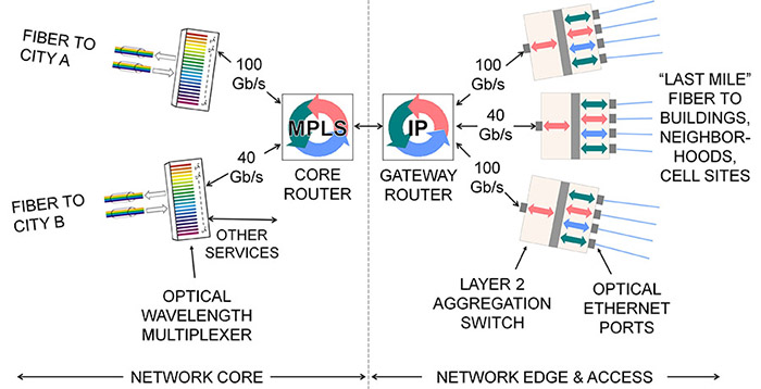
Figure 121 provides a closer look at the architecture of a core network node.
DWDM (Section 10.4) is used on core fibers to increase the capacity connecting routers in different cities to bit rates measured in the Terabits per second.
A gateway router is placed as a point of traffic control between access circuits on the right and the core router on the left. This gateway router also implements MPLS (Chapter 17), which is used to manage capacity on the network circuits.
Terminating a physical fiber means plugging it into an Optical Ethernet SFP transceiver inserted in a hardware port in a rack-mount device.
Routers are built with a relatively small number of hardware ports between which they can relay packets at line speed. Some of these ports would terminate core fibers, and others terminate connections to aggregation devices for access fibers via that node’s gateway router as illustrated in Figure 121.
Layer 2 switches (Section 15.4) with up to hundreds of Optical Ethernet hardware ports each are used to terminate the access fibers, which can number in the thousands.
Layer 2 switches are also data concentration or aggregation devices, interspersing traffic from all of the access circuits into high-speed streams to feed to the router. Everything works in both directions at the same time.
Layer 2 switches also implement VLANs (Section 15.5), a critical tool for segregating different users on the same access fibers in cooperation with additional Layer 2 switches connected downstream, as described in the next section.
– – –
This is one small piece of Telecom 101.
Join thousands of satisfied customers, and get the entire book today!