The same day I came across this by accident, today, fourteen years later, I am getting Bell Fibe TV installed, which is exactly what I was talking about in the video clip!
Broadband high-speed Internet service (25 Mb/s) with IPTV over DSL over the phone line for content delivery.
The term “port” crops up in IP networking, particularly in the context of rules in routers and software firewalls. One hears about “opening a port on a firewall” and “TCP ports” and “UDP ports”.
So just what is a “port”, exactly?
Like about 40% of the words in English after the Norman invasion of southern England following the Battle of Hastings in 1066, the English word “port” is French. Une porte is a door.
Of course, the French got it from Latin: porta (gate, door). The Latin word portus (port, harbor, and earlier, entrance, passage) and the Greek word poros (journey, passage, way) are obviously related.
In the computer hardware business, a port is a doorway into the machine: a jack, where a cable can be connected. In days past, there were serial ports and parallel ports on PCs. Today, we have USB ports and LAN ports. Technicians talk about connecting customers to ports on access equipment, for example, equipment with banks of modems.
In the computer software business, a port can be thought of as a doorway into the software running on the machine, a passageway to a specific computer program running on the computer.
Why is this necessary? Since there can be many computer programs (a.k.a. applications, apps) running on the same computer at the same time, when trying to communicate to a particular program, we require a mechanism to identify it, a way of telling the host computer to which program to relay our communications.
For example, we all know that it’s possible to have multiple applications using the Internet connection on a computer at the same time. Think of an Outlook email program and a Chrome browser program running at the same time on a PC connected to the Internet.
When data arrives at this computer, how does the computer know whether this data is for the email program or for the browser program? And how does it convey the data to the correct program?
The answer: every program is assigned a number called a port number. Your browser is assigned port 80, for example.
Here’s how it works: the sending program creates a message and tags it with the port number identifying the program it wishes to communicate with on the destination computer. This is put in a packet that is tagged with the network address (IP address) of the destination host computer and transmitted. When the packet arrives at the destination computer identified by the IP address, this receiving computer looks at the destination port number and parks the message in a memory space associated with that port number. The program on the destination computer assigned that port number is constantly checking that memory space to see if there is anything new waiting for it.
The result is the ability for a computer program running on one computer to communicate with a specific computer program on another computer.
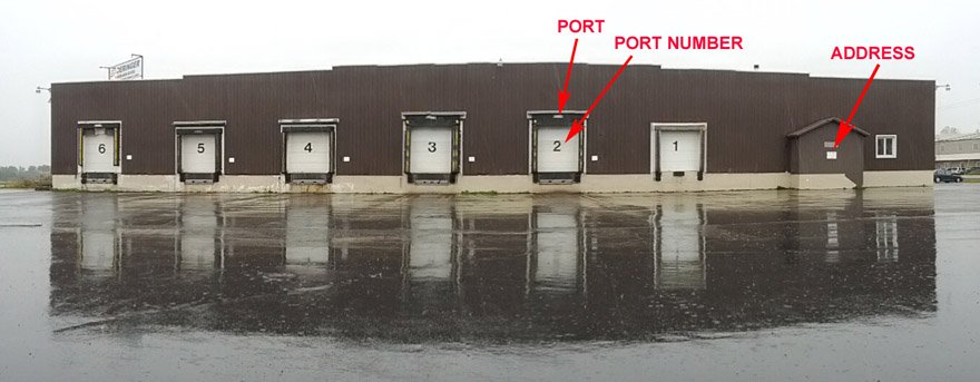
Visiting our warehouse service a couple of weeks ago, I was struck by the analogy possible between the idea of computer ports and a multi-tenant warehouse, so whipped out my Android smartphone and took a picture with the totally cool panoramic feature.
The warehouse is analogous to the host computer. It has a single street address. It handles goods for multiple users. Users have space allocated inside the warehouse. The warehouse has (on this side) six ports, also called loading docks. Each port has a number. A user can be assigned a port, either temporarily or permanently.
To communicate goods to that user, they’re carried in a shipping container (IP packet) on a truck (Ethernet frame) over a road (LAN cable) to the warehouse at its street address (IP address). To get the contents of the shipping container delivered to the correct user, the truck is backed up to the appropriate loading dock (port) identified by its door number (port number) and the contents of the container are unloaded to the space behind that port.
In computer communications today, the port number is 16 bits long, and the source and destination port number are populated at the beginning of the transport layer header, Layer 4 of the OSI model. The world’s most popular standard protocols for implementing the transport layer are the TCP (Transmission Control Protocol) and UDP (User Datagram Protocol).
Hence, one hears of “TCP ports” and “UDP ports”, particularly when configuring rules for packet forwarding on a router or firewall. When one “blocks” a port, that means that communication to a particular computer program is denied. When one “opens” a port, communication to that computer program is being allowed.
Standard practice is to allow communications only to specifically-identified ports and deny all other communications.
The port number of the application and the IP address of the host computer concatenated together is called a socket in UNIX and IP and is called a transport service in the OSI model. The result is the ability to identify the specific source computer program on one computer and the specific desired destination computer program on a different computer.
Join Teracom Training Institute’s affiliate sales program, advertise Teracom Online Courses and Certifications on your website, and earn a commission on every student you refer who registers for Online Courses and Certifications!
Teracom is the leader in telecom and network training courses, developed and refined over twenty years. Teracom training courses now available online are top-notch, top-quality and right up to date.
We’ve partnered with the Telecommunications Certification Organization for certifications. Students register for a Certification Package, which includes courses and certification exams, complete the courses and exams, and earn TCO Certification, with diploma, letter of reference and more.
To be accepted as a Teracom Sales Affiliate, you’ll need to have an established web site or blog with sufficient daily page views by unique visitors, and place descriptive text and graphics describing Teracom courses on your site.
Not only will you earn 20% of net proceeds from students who are referred from your site, becoming a Teracom Training affiliate adds prestige to your site, and may complement other content on your site or add to other training affiliations you may have, making your site in turn more valuable.
There is no cost to become a Teracom Sales Affiliate. There are, of course, terms and conditions that must be respected, including a minimum sales level that must be maintained to remain in the program.
To begin the process of becoming a Teracom Sales Affiliate, please complete the “contact us” form, stating that you would like to apply to join the Teracom Affiliate Sales Program, and include the address of your website.
The Internet connection at your office dies. Lights on your modem are flashing in a strange pattern. You call the ISP, and they quickly diagnose that the modem power supply has failed, and they will overnight you a replacement. Presumably you are not the first person to have this problem with that modem.
So how do you continue to operate while you are waiting for the replacement power supply? It’s hard to run your business without e-mail and ordering and administration systems, which are all accessed via the Internet.
If you want availability, you need two connections to the Internet, so if one fails you are not out of business. We go over this in the lesson “Mature Competitive Carrier Network: Regional Rings, POPs and MANs”, slide 3.17 of Course 101, Telecom Datacom and Networking for Non-Engineering Professionals, and mention it in pretty much every other course.
A large business will be a station on a Metropolitan Area Network, which is a ring, meaning two connections to the Internet for that business and automatic reconfiguration in the case of one failing. But this is expensive… the second connection is not free.
Small and medium businesses usually have a single DSL or cable modem connection to the Internet. When that fails, connectivity to email, ordering and administration servers is impossible, and many businesses these days would be “dead in the water” until the ISP fixes the problem with their hardware.
Unless you have an Android smartphone, a good “data” plan and a laptop with WiFi running Windows.
The scenario described happened at our office last week. Since many of our customers might find themselves in a similar situation – even at home – I thought I’d share the quick and painless solution I came up with. Even if you’re not likely to need this solution, understanding how it works will no doubt sharpen your understanding of the devices involved and their functions.
In this tutorial, I will use the technology in our office: 16 Mb/s DSL, Android smartphone and Windows laptop. The solution is equally applicable to an Internet connection using a cable modem or if you are one of the lucky few, an Internet connection via fiber.
For the smartphone and laptop, there may be equivalent functions on Apple products, but as I am allergic to Apples, we don’t have any in the office. I’m posting this tutorial on our Facebook page, our Google+ page, or our blog; I invite someone better able to tolerate Apple products to leave a comment whether and how the iPhone and MacBook can perform the required functions.
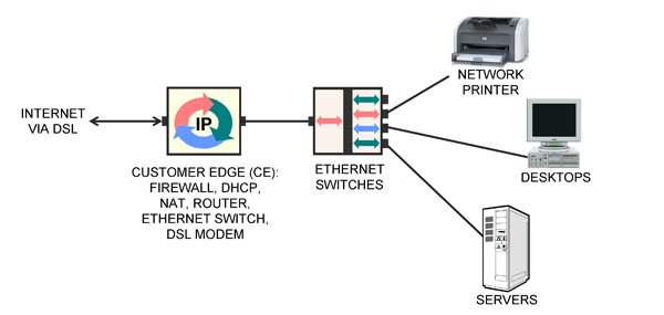
Figure 1: Normal network setup
Figure 1 illustrates the normal network setup in our office, a typical configuration for networking at a small or medium business. On the left is the access circuit to the Internet Service Provider (ISP), terminating on a modem in our office.
The modem is contained in a box that also includes a computer and an Ethernet switch. This box is more properly called the Customer Edge (CE).
The computer in the CE runs many different computer programs performing various functions: Stateful Packet Inspection firewall, DHCP server offering private IP addresses to the computers in-building, DHCP client obtaining a public IP address from the ISP, a Network Address Translation function between the two, routing, port forwarding and more.
In-building is a collection of desktop computers, servers and network printers. These are connected with Category 5e LAN cables to Gigabit Ethernet LAN switches, one of which is also connected to the CE.
When a desktop computer is restarted, its DHCP client obtains a private IP address and Domain Name Server (DNS) address from the DHCP server in the CE. The private address of the CE is configured as the “default gateway” for the desktop by Windows.
When a desktop computer wants to communicate with a server over the Internet, it looks up the server’s numeric IP address via the DNS, then creates a packet from the desktop to the Internet server and transmits it to its default gateway, the CE.
The NAT function in the CE changes the addresses on the packet to be from the CE to the Internet server and forwards the packet to the ISP via the modem and access circuit. The response from the Internet server is relayed to the CE, where the NAT changes the destination address on the return packet to be the desktop’s private address and relays it to the desktop.
The solution for restoring Internet access after the CE died is illustrated below.
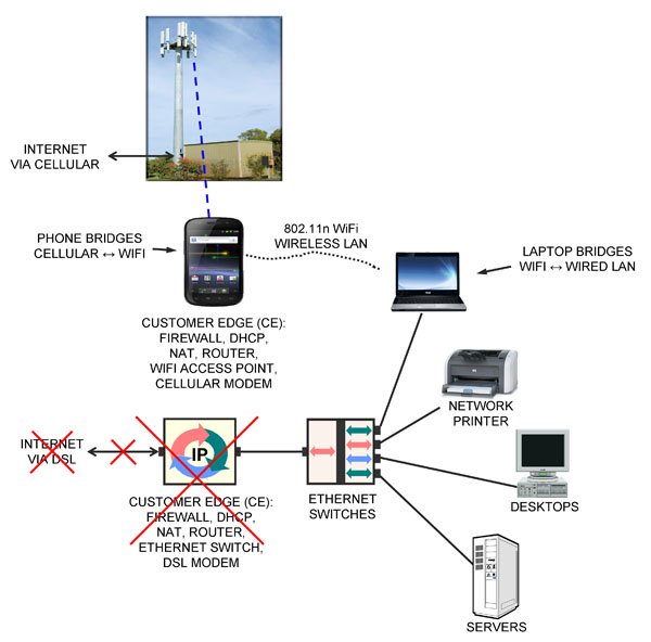
Figure 2 Restored Internet Access via Cellular
An Android smartphone and a laptop running Windows were used to restore connectivity to the Internet without making any changes to the desktops, servers or network printers.
First, I took my Samsung/Google Nexus smartphone running Android out of my pocket and plugged in the charger.
Then on its menu under Settings > more > Tethering & portable hotspot > Set up Wi-Fi hotspot, I entered a Network SSID (“TERACOM”) and a password, clicked Save, then clicked Portable Wi-Fi hotspot to turn it on.
The smartphone is now acting as a wireless LAN Access Point, just like any other WiFi AP at Starbucks, in the airport or in your home.
At this point, the smartphone is the CE device, performing all of the same functions that the DSL CE device had been before it died: firewall, DHCP client to get a public IP address from the ISP (now via cellular), DHCP server to assign private IP addresses to any clients that wanted to connect (now via WiFi), NAT to translate between the two and router to forward packets.
Just as the DSL CE equipment “bridged” or connected the DSL modem on the ISP side to the Ethernet LAN in-building, allowing all the devices on the LAN to send and receive packets to/from the Internet via DSL, the smartphone “bridges” or connects the cellular modem on the ISP side to the WiFi wireless Ethernet LAN in-building, allowing all the devices on the wireless LAN to send and receive packets to/from the Internet via cellular radio.
The remaining problem was that none of the desktops or servers had wireless LAN cards in them, so they could not connect to the smartphone AP and hence the smartphone’s cellular Internet connection.
What was needed was a device to “bridge” or connect the wired LAN to the wireless LAN in-building. By definition, this device would need two LAN interfaces: a physical Ethernet jack to plug into the wired LAN, plus a wireless LAN capability.
Looking around the office, I spotted two devices that fit this description. One of them was my laptop, with both a LAN jack and wireless LAN.
I fired up the laptop, plugged it into an Ethernet switch with a LAN cable, and in the Network and Sharing Center, clicked Change Adapter Settings to get to the Network Connections screen that showed the two LAN interfaces.
I enabled both the wired and wireless LAN interfaces. Then right-clicking the Wireless Network Connection icon, selected the TERACOM wireless network and entered the password.
Once that was successfully connected, I selected the two adapters in the Network Connections screen, right-clicked and chose “Bridge Connections”. A message saying “Please wait while Windows bridges the connections” appeared, then an icon called “Network Bridge” appeared, and after a few seconds, “TERACOM” appeared as well.
My laptop was now acting as an Ethernet switch, connecting the wired LAN to the smartphone’s wireless LAN.
Each of the desktops, servers and network printers in the office had to be rebooted so they would run their DHCP client again, obtaining a private IP address and DNS address from the smartphone AP, and be configured so the smartphone was the “default gateway” in Windows.
After rebooting my desktop computer, it had Internet access over the wired LAN, through the wired Ethernet switch to my laptop, to the smartphone via WiFi then to the ISP over cellular.
After rebooting the other desktops and servers, all had Internet access again, with no changes to the configuration of the desktops or servers.
This took about 20 minutes to get up and running, and we were back in business. Running a bandwidth test on speedtest.net, I found we had exactly 5 Mb/s connection to the Internet via cellular.
Obviously my cellular service provider limited the connection to 5 Mb/s in software – but who’s complaining? 5 Mb/s is more than three times as fast as a T1, which cost $20,000 per month when I first started in this business 20 years ago.
I hope you found this tutorial useful, either as a template for your own emergency backup Internet connection, or simply as a way of better understanding the devices, their functions and relationships.– EC
Note 1: You must verify your billing plan for “data” on your cellular contract before doing this. I have 6 GB included, which means basically unlimited, and that includes the WiFi hotspot traffic. Make sure you have something similar, to avoid receiving a bill for $10,000 for casual “data” usage.
Note 2: As always, this tutorial is provided as general background information only. We do not guarantee it will work for you. Each situation is unique and requires professional advice to identify and resolve issues including but not limited to performance and security. This tutorial is not professional advice. But I hope you have found it valuable.
Note 3: I might have been able to implement this without the laptop. If you’d like to know that, or what was the other device I could have used to bridge the wired and wireless LAN in-building, or suggest how this could be done with Apple products, please leave a comment.
Happy birthday IP version 6 – you finally arrived!
World IPv6 Launch Day was June 6, 2012 (about 12 years later than originally planned).
Hundreds of companies permanently enabled IPv6 protocol stacks on their servers on June 6, allowing the small percentage of devices (primarily Android smartphones) that had applications, operating systems and carriers all supporting IPv6 to communicate IPv6 packets end-to-end.
The address fields in IPv6 packets are 128 bits long, meaning 2 to the power 128 addresses.
Forget about questions like “how long is eternity going to last for”, “how far is it to the other side of the universe?”, “what happened before the Big Bang”, “where did all that energy come from in the first place?”, “who is God’s God?, and “who is God’s God’s God?”; we humans are not capable of understanding 340,282,366,920,938,463,463,374,607,431,768,211,456.
Teracom Instructor Richard Olsen did some calculations to help us grasp this number, including calculating how many grains of sand there are in the Earth’s crust. (Can you tell Richard is an Engineer?)
I’ll let Richard tell the story in his own words:
“I was teaching at Motorola University circa 1998 and in discussing IPv6, a student said, ‘You know, there are enough IP addresses in IPv6 for every square inch of the Solar System.’ I thought, that’s crazy, he’s out of his mind. I just said, ‘Wow!'”
“Anyway, while flying home I thought, I wonder how many square inches there are in the Solar System anyway. I think I’ll figure that out when I get home.”
“First I had to decide what ‘square inches of the Solar System’ meant. I decided to use the surface area of all the planets in square inches. That didn’t even come close to the number of IP addresses in IPv6.
I decided to throw in the Sun because that sucker is really big. Didn’t even come close. Then I decided to use the square inches inside the orbit of Pluto (this was before Pluto got kicked out of the Planet Club – poor Pluto!). Still didn’t even come close.”
“Finally, I’d always heard “IPv6 has enough IP addresses for every grain of sand on all the beaches on Earth”. By this time, I knew that couldn’t be. So I finally decided to calculate IP addresses per grain of sand over the entire surface of the Earth, including under the oceans, one mile deep assuming 10,000 grains of sand per cubic inch.”
“Answer: an astounding 664 BILLION IP addresses per grain of sand. Now, that’s a big number!!”
“The most commonly quoted number of stars in a galaxy is 100 billion and the most commonly quoted number of galaxies in the Universe is 100 billion. Assuming there are 10 planets around every star, then there are 10 x 100 x 100 billion billion planets in the Universe.
So how many IP addresses per planet in the entire Universe? Answer: 3.4 quadrillion IP addresses per planet!”
“The number of IP addresses in IPv6 is truly a prodigious number.”
I’ve told Richard’s story many times in classes. Over the years, like all good stories, it became embellished, and the story became
“666 billion addresses per grain of sand in the Earth’s crust to a depth one mile deep”, and “more addresses than there are square inches on the sphere that encloses the solar system out to Pluto.”
After reading Richard’s story again recently, I figured I had better verify the last claim, so I asked Richard to calculate the number of square inches on the sphere that encloses the solar system out to Pluto and divide that into 2**128.
It turns out my embellishment was not wrong: there are 5 millon addresses per square inch on the sphere that encloses the solar system out to Pluto.
Hope this all helps you grasp the number 340,282,366,920,938,463,463,374,607,431,768,211,456.
MPLS and Carrier Networks is a comprehensive training course designed to build a solid understanding of carrier packet networks and services, the terminology, technologies, configuration, operation and most importantly, the underlying ideas… in plain English.
This course can be taken by both those who need simply an overview and introduction to the fundamentals of carrier packet networks and MPLS, and by those who need to get up to speed and establish a solid base that project or job-specific knowledge can be built on.
We’ll cut through the buzzwords and marketing to demystify carrier packet networks and services, explaining Service Level Agreements, traffic profiles, virtual circuits, QoS, Class of Service, Differentiated Services, integration, convergence and aggregation, MPLS and other network technologies, and how they relate to TCP/IP without bogging down on details.
You will gain career- and productivity-enhancing knowledge of the structure, components and operation of carrier packet networks and services, how they are implemented, packaged and marketed by carriers and how they are used by government, business… and other carriers.
We’re getting ready to release another Online Course at the end of March: L2014 “MPLS and Carrier Packet Services.”
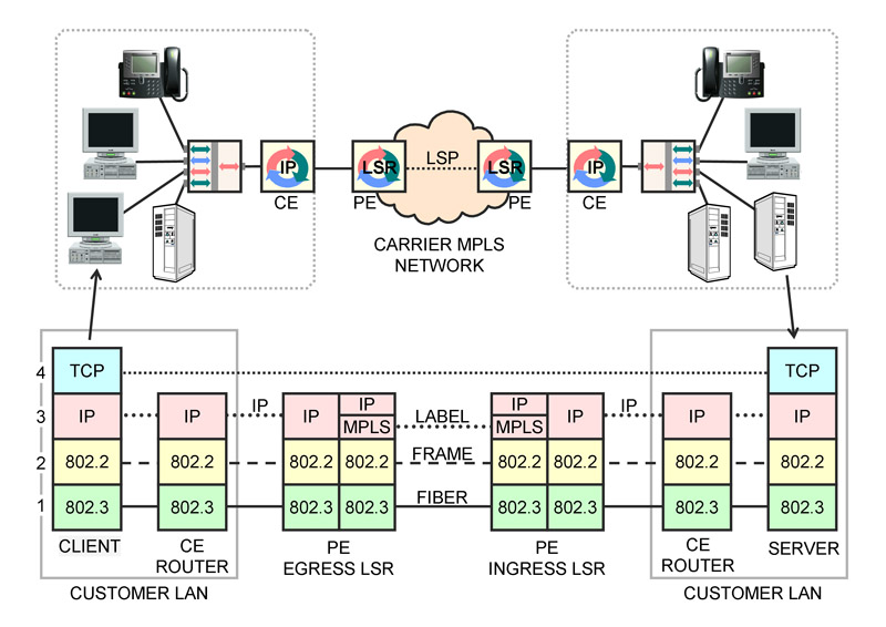
As a sneak preview, this newsletter’s free tutorial is part of Lesson 11 “TCP/IP over MPLS” from that course.
NOTE: You may find this tutorial a bit overwhelming, landing smack on your computer screen with no preparation, like a parachutist whose chute didn’t open landing in a cow field.
In the Online Course “MPLS and Carrier Packet Services”, there are TEN lessons building up to this one.
The tutorial is part of the text and one graphic from Lesson 11 “TCP/IP over MPLS”. The Online Course when released at the end of March will have extensive animations following along with a voiceover of the text. Enjoy!
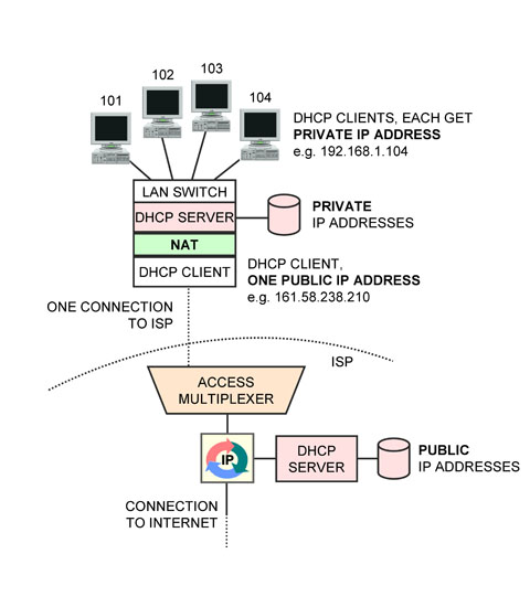
In lessons leading up to this one, we cover private IP addresses, and why these are preferable to use on an in-building network.
However, if any of the users on the private network want to receive packets from the Internet, a public IP address is required.
The question we explore in this lesson is how to enable Internet communications for all users in-building without having to rent a public IP address for every user?
A solution is to use a Network Address Translator (NAT).
When a computer on the private side initiates communications with a server, it populates the source IP address field in the packet header with its private address and the destination IP address field with the public IP address of the server.
The packet is then transmitted in a MAC frame to the computer’s “default gateway”, which is the Customer Edge router. This device is performing the NAT function.
The NAT changes the source IP address from the private IP address of the sender to the public IP address of the NAT, i.e. the CE router, then transmits the packet in a frame on the public network (the Internet).
The Internet server of course uses the source address in the packet it receives as the destination address to answer back to the client. Therefore, it will send the response back addressed to the NAT.
When the NAT receives the packet, it changes the destination IP address on the packet received from the Internet to the private IP address of the appropriate computer, then transmits the packet in a MAC frame to the computer.
One question that arises is: how does the NAT know what computer on the private network a packet received from the Internet is intended for?
It turns out that the NAT uses the Layer 4 header to keep track of things. The Layer 4 header (TCP or UDP) begins with two octets that are called the “source port” then two octets for the “destination port”. These fields are used to indicate which application on a computer the message is being sent from and to.
The NAT selects an arbitrary “fake” port number to identify a computer on the private network, and records this port number against the private address in a table.
When a packet is transmitted to the Internet, the NAT records the actual source port number then changes the source port value to the “fake” port number.
When the reply from the server is received from the Internet, it has the “fake” port number in the destination port field of the Layer 4 header. The NAT uses this to look up the correct private IP address and correct port number and enter those values in the destination address and destination port number fields, thus relaying the incoming packet to the correct computer on the private network.
NAT provides a number of advantages:
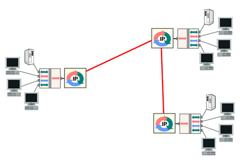
1. A NAT allows multiple computers in-building to share a single Internet address and Internet connection.
2. A NAT provide a truly “always-on” connection to the Internet. Services like DSL and Cable modem described as “always on” are always connected at the Physical Layer. They do not provide “always on” at the Network Layer, since DHCP must be run every time the attached device restarts to get a public IP address.
When a NAT is inserted, it runs DHCP to get the public IP address; so if the NAT is not powered off, the site will always have a public IP address assigned, and thus a connection to the Internet always ready for immediate use.
3. A NAT shields machines from attacks from the Internet. Since a private IP address is not reachable from the Internet, there is no way for a machine on the Internet to initiate communications to a machine on the private network. The only device exposed to the Internet is the NAT. Normally, the NAT is not running on a computer running Windows, so attackers have a greatly diminished chance of finding an vulnerability to exploit compared to connecting a computer running Windows naked onto the Internet.
Devices that perform this function are available in industrial-strength versions from companies like Cisco. Hardware devices to do this are also available for about $20 from companies like Linksys for use on a DSL or cable modem connection. They often include both an Ethernet switch and an 802.11 wireless LAN access point for the private network side. Most ISPs now provide the CE router with NAT function integrated in a device that includes the DSL or Cable modem they supply.
In this course, we concentrate on the fundamentals of IP packet networks, routers and IP addresses.
Packet networks embody two main ideas: bandwidth on demand and packet switching.
First, we’ll recap channelized TDM and its limitations, then understand statistical TDM or bandwidth on demand.
Next, we’ll understand how routers implement the network with packet-switching, that is, relaying packets from one circuit to another, and how routers are a point of control for network security. We’ll introduce the term Customer Edge (CE).
Then we’ll cover the many aspects of IP addressing: IPv4 address classes, dotted decimal notation, static vs. dynamic addresses, DHCP, public vs. private addresses, Network Address Translation, IPv6 overview and finish with IPv6 address allocation and assignment.
1. Module Introduction watch now (free)
2. Review: Channelized Time-Division Multiplexing (TDM)
3. Statistical Time-Division Multiplexing: Bandwidth-on-Demand
4. Private Network: Bandwidth on Demand + Routing
5. Routers
6. IPv4 Addresses
7. DHCP
8. Public and Private IPv4 Addresses
9. Network Address Translation watch now (free)new tutorial!
10. IPv6 Overview
11. IPv6 Address Allocations and Assignment
Overall objective
The objective of this course is to develop a solid understanding of IP. After taking this course, you will be up to speed on the fundamental principles of packet networks: bandwidth on demand, also known as overbooking or oversubscription, and packet forwarding. You will know the IP packet format and how IP addresses are allocated, assigned and displayed. You will know the difference between static and dynamic addresses, public and private addresses and how Network Address Translation works. An additional objective is to become familiar with the basics of IPv6.
Learning Objectives Upon completion of this course, you will be able to explain:
The concept of statistical multiplexing, also known as oversubscription, overbooking and bandwidth on demand, why and how it can be implemented and its benefits.
What a private network is
What a router is and how it implements the network by connecting data links
How routers move packets between broadcast domains, including VLANs
How routers also act as a point of control for traffic, called packet filtering
The basic structure and contents of a routing table
The Customer Edge
IPv4 address blocks: Class A, Class B and Class C, and dotted-decimal notation
Static addresses and dynamic addresses, and how and why DHCP is used to assign both
Public addresses and private addresses, how, why and where each is used
Network Address Translation for interfacing domains where public addresses are used with those where private addresses are used
The improvements and changes between IPv4 and IPv6, and
The types of IPv6 addresses, how IPv6 addresses are allocated to ISPs then assigned to users, and how each residence gets 18 billion billion IPv6 addresses.
List of Lessons
Lesson 1. Course Introduction (this one).
Lesson 2. Review: Channelized Time-Division Multiplexing (TDM)
We’ll review the idea of channelized Time-Division Multiplexing, what channels are, and how they can be used to aggregate traffic onto a high-speed circuit. Then we’ll raise some questions: is that an efficient way to connect devices that produce traffic in bursts, which means devices that are normally doing nothing? And what about the problem of a single point of failure for all the aggregated traffic? Subsequent lessons explore the answers to those questions.
Lesson 3. Statistical TDM: Bandwidth-on-Demand.
In this lesson, we’ll understand how circuits that move bits constantly can be used efficiently when the user’s traffic profile is: “idle most of the time, interspersed with bursts of data every once in a while.” The answer is overbooking. This is also called statistical multiplexing and bandwidth-on-demand, and is a key part of a packet network: the internal circuits are heavily overbooked, to give users the highest speed at the lowest cost. It is necessary to know the users’ historical demand statistics – also called their traffic profile – to know how much to overbook, hence the term statistical multiplexing.
Lesson 4. Private Network: Bandwidth on Demand + Routing.
The purpose of this lesson is to expand the discussion of the previous lesson to include multiple circuits. The result is called a private network, and is the simplest framework for understanding routers, routing, network addresses and bandwidth-on-demand.
Lesson 5. Routers
In this lesson, we’ll take a closer look at a router, more precisely identifying the functions a router performs to implement a packet network, and understand how a router routes by examining the basic structure and content of a routing table. We’ll also understand how the router can act as a point of control, denying communications based on criteria including network address and port number, why this is implemented and its limitations. The term Customer Edge (CE) is defined in this lesson.
Lesson 6. IPv4 Addresses
Here, we’ll understand IPv4 addresses, address classes and the dotted-decimal notation used to represent them.
Lesson 7. DHCP
In this lesson, we’ll cover DHCP: the Dynamic Host Configuration Protocol, and understand the mechanism by which a machine is assigned an IP address. We’ll also understand how the “dynamic” host configuration protocol can be used to assign static addresses to machines and the advantages of this method.
Lesson 8. Public and Private IPv4 Addresses
The purpose of this lesson is to define the terms “public” and “private” IP address, review how IP addresses are assigned and the costs for those addresses, then cover the ranges of IPv4 addresses that are used as private addresses, and understand how and why they are used.
Lesson 9. Network Address Translation
In this lesson, we’ll explore how private IPv4 addresses used in-building and a public address required for Internet communications can be joined together with a software function called Network Address Translation.
Lesson 10. IPv6 Overview
Completing this course on IP, we’ll first review the next generation of IP: IPv6, understand the improvements compared to IPv4 and review the format of the IPv6 packet and its header.
Lesson 11. IPv6 Address Allocations and Assignment
Finally, we examine the structure of the 128-bit IPv6 address, review the different kinds of IP addresses, the organizations that allocate them, and the current plans for how addresses will be assigned to end users… and how every residence gets 18 billion billion IPv6 addresses.
Waiting for a flight at the airport. Time on my hands, I try out a feature included with the Android operating system on my new Samsung Galaxy: create an 802.11g Wireless LAN (WiFi) base station on the phone.
This WiFi network is automatically bridged inside the phone to the Internet connection provided by the cellular carrier.
Easy step-by-step instructions were included on the setup screen.
Fired up my laptop and found the WiFi network and connected no problem.
In fact, I sent a post to Google’s servers over the very link!
Ain’t technology wonderful.
Bonus: your car can now be a WiFi hotspot! You could even get a WiFi hotsopt logo sticker and put it on your back window, like Greyhound… On a long car trip with my family, all of whom have WiFi enabled iPhones, iPods, DSs etc. etc., I can tell them the WiFi password, and they can share my internet connection.
Double bonus: If the kids start squabbling, I can threaten to turn it off!
btw, I have 6 GB/month in my plan, so not so worried about usage-based pricing for the connection. Best check your billing plan before trying it.


 In this course, we concentrate on the fundamentals of IP packet networks, routers and IP addresses.