BOOT CAMP is running strong during the pandemic Live Online!
All you need to join BOOT CAMP Live Online and get this
world-famous training is Internet, a laptop with a webcam and Zoom.
We’ll ship you the high-quality printed color course books in advance of the BOOT CAMP, and you’ll be part of a class that runs 9 – 5 ET Monday – Friday.
The best part: BOOT CAMP was totally updated for 2020, with 5G,
Cloud Computing, Data Centers, Smart Cities & more, just before the
pandemic struck! This is the most up-to-date telecom-for-non-engineers
training that can be found anywhere. This is truly career-enhancing
knowledge.
Teracom BOOT CAMP Live Online is a great opportunity:
Live interactive group training, guaranteed coronavirus-free!
You will be part of a class.
You will be able to see and hear everyone else.
We’ll ship you the high-quality printed color course books in advance.
The instructor will teach the class like any other BOOT CAMP.
The instructor will keep you focused, so you learn, like any other BOOT CAMP.
You can ask the instructor questions, like any other BOOT CAMP.
The class will run on a schedule: 9 – 5 ET Monday to Friday, with scheduled breaks, like any other BOOT CAMP.
You get immediate access to three TCO Certification Packages, with their online courses.
No travel required.
Anyone worldwide can take BOOT CAMP.
All you need is a laptop with a webcam.
Get the training you need!
You’ll get the course materials shipped to you: two printed color
books totaling over 500 pages with copies of all graphics and detailed text
notes. You will also get immediate access to the included TCO
Certification Packages: CTNS, CTA and CVA and their twenty full-length online
courses, with no time limits and unlimited repeats.
You’ll get the full BOOT CAMP with a live instructor, as close as you can get without actually being there.
If you are an international participant, this is your opportunity
to take BOOT CAMP if you can’t travel to the USA for a public seminar. No
travel visa required!
New Course 2241 Introduction to Broadband Telecommunications along with existing Course 2221 Fundamentals of Voice over IP will be added to the CTNS Certification Package before year-end.
The price of the CTNS package will increase when the number of courses increases from six to eight. Since all existing customers will automatically get the two new courses at no additional charge, you can beat the price increase by purchasing CTNS before the upgrade and get the two new courses, when they are released, for free!
Wireless Telecommunications is a comprehensive course on wireless, mobile telecommunications plus wireless LANs and satellites.
We begin with basic concepts and terminology including base stations and transceivers, mobile switches and backhaul, handoffs, cellular radio concepts and digital radio concepts.
Then, we cover spectrum-sharing technologies and their variations in chronological order: GSM/TDMA vs. CDMA for second generation, 1X vs. UMTS CDMA for third generation along with their data-optimized 1XEV-DO and HSPA, how Steve Jobs ended the standards wars with the iPhone and explaining the OFDM spectrum-sharing method of LTE for 4G.
This course is completed with a lesson on WiFi, or more precisely, 802.11 wireless LANs, and a lesson on satellite communications.
You’ll gain a solid understanding of the key principles of wireless and mobile networks:
• Coverage, capacity and mobility
• Why cellular radio systems are used
• Mobile network components and operation
• Registration and handoffs
• Digital radio
• “Data” over cellular: Internet access
• Cellular technologies: FDMA, TDMA, CDMA, OFDM
• Generations: 1G, 2G, 3G, 4G
• Systems: GSM, UMTS, 1X, HSPA, LTE
• WiFi, 802.11 wireless LANs
• Satellite communications
It is important to understand how packets and frames are related, and in particular, IP packets vs. Ethernet or MAC frames.
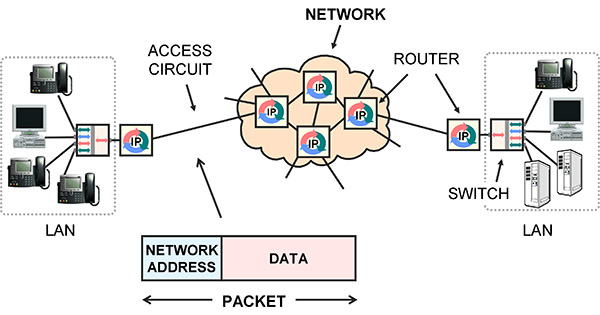
Simple network example. Routers move packets from one circuit to another.
Packets are for networks. A packet is a block of user data, such as a piece of an e-mail message, with a network address on the front. The network address is the final destination. The standard for network addresses is IP.
Network equipment like routers receive an IP packet on an incoming circuit, examine the indicated destination IP address, use it to make a route decision, then implement the decision by forwarding the packet to the next router, on a different circuit.
A frame is a lower-level idea. Frames are used to communicate between stations on the same circuit. The circuit may have multiple stations physically connected onto it, like a wireless LAN, a few stations connected by a LAN switch, or only two stations like a point-to-point LAN cable. Each station has a Media Access Control (MAC) address, sometimes called a hardware address, link address or Layer 2 address.
A frame has framing to mark the beginning and end, sender and receiver MAC addresses to indicate the stations on the circuit, control information, a payload and an error detection mechanism.
The frame is transmitted on the circuit, and all stations on the circuit receive it. If an error is detected at a receiving station, the frame is discarded and might have to be retransmitted somehow.
If no errors are detected, the receiver compares the destination MAC address on the received frame to its own MAC address, and if they are the same, processes the frame, extracting the data payload and passing it to higher level software on the receiver.
If the MAC addresses are not the same, the receiver ignores it and waits for the next one.
The end result is that the payload in the frame is communicated to the correct station on the same circuit, with no errors.
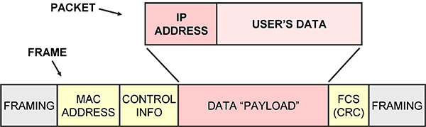
Packet with its IP address vs. frame and its MAC address
The main purpose of packets is to append an IP address to your data. The IP address is used by network equipment to make route decisions: to relay the packet from one circuit to a different circuit. This is accomplished by receiving the packet then transmitting it to a different machine, usually the next router in the chain.
To actually transmit a packet to another router, the packet is inserted as the payload in a frame, then the frame is broadcast on the circuit that connects to the next router.
Notice that there are two addresses: the IP network address and the MAC address.
The IP address on the packet is the final destination, and so does not change. The MAC address on the frame indicates the destination on the current circuit, and so is changed as the data is forwarded from one circuit to another.
A volunteer project to set up WiFi in a 150-year-old building with stone walls that I did recently required repeaters, also known as range extenders.
I ended up writing detailed instructions to get a popular WiFi access point / router on Amazon working as a repeater… and thought you might find this useful to extend WiFi coverage in your home or small office.
Even if you don’t need to extend your WiFi coverage, understanding the configuration, including the IP addresses, DHCP, subnets and all the other items covered in this tutorial is career-enhancing knowledge.
The requirement was to provide WiFi coverage in a 150-year old building with thick stone walls. The Internet connection (DSL) was in the basement, and coverage was required to the fourth floor.
We initially looked at pulling a cable to the fourth floor, but the stone walls made wireless a no-brainer.
The WiFi signal produced by the ISP’s Customer Edge device, which contains the DSL modem, a router, switch and WiFi Access Point, did not reach very far.
So WiFi repeaters, sometimes called Range extenders would be required. This had to be implemented with encryption of data over the air for information security.
Special-purpose range extenders can cost $300 each. After a bit of research, I bought these $20 units on Amazon.
They support “300 Mb/s” 802.11n, and most importantly, implement the Wireless Distribution Service (WDS) with WPA2 airlink encryption, which is needed for the repeater function with security.
The instructions weren’t very complete, so I looked at the product’s Q&A section on Amazon and found instructions.
But those instructions turned out to be not quite right. And being an Engineer, I couldn’t help but proposing correct instructions…
These instructions assume you are connecting the WiFi access point / router pictured, TP-LINK model TL-WR841N, to any WiFi with a working Internet connection.
Abbreviations:
[example] = example values used during my setup.
Yours might be a bit different.
SOURCE-AP = the access point / router generating the wireless signal you want to repeat. This is often supplied by your ISP.
REPEATER-AP = the access point / router repeating the wireless signal, the one that we are setting up.
SOURCE-NET = the SSID (network name) of the wireless signal you want to repeat.
REPEATER-NET = the SSID (network name) of the repeated wireless signal.
GUI = Graphical User Interface.
This is the access point / router’s control panel.
Before starting, gather the following information:
– The LAN/wireless side IP address of the SOURCE-AP GUI. [192.168.3.1]
– The username and password for the SOURCE-AP GUI.
[admin, admin]
– The subnet the SOURCE-AP is using on the LAN/wireless side. [192.168.3.x]
– The SOURCE-NET name [GROUND]
– The encryption type and password [WPA-2 PERSONAL, xxxx]
– The channel the wireless signal to be repeated is on. [3]
If you don’t know the channel, you can find out during the setup below. However, it is preferable to log in to the SOURCE-AP GUI and set the channel to 3 instead of “auto” so it does not change, and uses an unpopular channel likely to have less interference.
To determine the LAN/wireless IP address and subnet of the SOURCE-AP, look at the IP address and default gateway of a device directly connected to the SOURCE-AP. (Open the Network connections folder, click change adapter settings, and view status and then details in Windows). The value in the default gateway field is the IP address of the SOURCE-AP GUI. The part of the address common to the default gateway and the device is the subnet ID.
Do this setup and get it working somewhere comfortable near the SOURCE-AP. Once it’s working, you can place the repeater anywhere near an electrical outlet.
Here we go:
1. Plug the power into the REPEATER-AP. If any settings have already been changed on the device, press and hold the reset button on the back for ten seconds until all lights are illuminated to indicate reset happening. Reset is not necessary if the unit is fresh out of the box.
2. Plug a PC into a LAN port on the REPEATER-AP with the supplied LAN patch cable. I used my laptop. Make sure the LAN adapter is set to get an IP address automatically. (Open the Network connections folder, click change adapter settings, and view properties in Windows). Make sure the LAN adapter is the only one enabled. Disable the wireless adapter.
3. Open a browser and go to http://tplinklogin.net . This gets you to the GUI of REPEATER-AP, initially 192.168.0.1. The default username, password is admin, admin. Don’t do the quick setup.
4. Click “Wireless” on the left column menu.
On the Wireless Settings page that appears:
a. Under the dropdown list for “Channel”, select the channel the wireless signal to be repeated is on. [3] If you don’t know, skip this step and the unit will force you to select the correct one after the “Survey” step below.
b. Click the “Enable WDS bridging” checkbox.
c. Click “Survey”. A list of SSIDs appears. Click “connect” on the one that is SOURCE-NET. [GROUND] All of the fields are automatically populated except for the password.
d. Enter the password and click Save. Wait ten seconds for the processing to finish.
e. At the top of the page beside Wireless Network Name, enter a name for REPEATER-NET [R1] and click Save.
5. Click “Wireless Security” on the left column menu. Select Personal WPA2-PSK, AES encryption and enter a password for REPEATER-NET.
6. Click “DHCP” on the left column menu. Click the DHCP disable radio button. Click Save. Ignore the reboot warning.
7. Click “Network” on the left column menu.
8. Click LAN. Change the IP address to one in the SOURCE-AP subnet that is not being used by any other device and click Save [192.168.3.200]. A reboot warning will appear. Click OK and let the unit reboot.
9. The address in the browser will magically change to the IP address you entered in the previous step. This is the new IP address for the GUI on REPEATER-AP. You will be prompted to log in again. The status screen will appear. Under Network, click the WAN MAC menu item on the left.
You should also now have Internet through REPEATER-AP!
Open news.google.com in a new tab in your browser to verify.
Wireless devices can now connect to REPEATER-NET.
Wired devices can connect to REPEATER- AP.
Both get Internet access through SOURCE-AP.
Ain’t life grand?
10. To avoid problems with dynamic addresses and timeouts, make the IP address of REPEATER-AP static.
Open a new tab in your browser. Enter the address of the SOURCE-AP GUI [192.168.3.1] and log in. Find the screen that lets you assign static IP addresses. The SOURCE-AP could be any brand of device; it is often supplied by your ISP. The function might be called “DHCP reservations” or “IP address reservation”. Make a new entry, with the WAN MAC address displayed in the REPEATER-AP GUI and the REPEATER-AP IP address you entered in Step 8.
I actually set up a chain of four of these units to provide wireless coverage from the basement to the fourth floor of a 150-year-old building with stone walls. And it worked!
Good luck!
P.S. Don’t forget to go back in to REPEATER-AP and change the password. The menu item is hiding under System Tools on the left.
Notice required by the legal department: This information is provided as general background information only. Design and implementation of a communication system requires professional advice to identify and resolve issues specific to that particular system, including but not limited to performance, availability and security issues. Additionally, while we have strived to be as accurate as possible, we make no representation or warranty that the information provided is 100% accurate. This information is not to be relied upon as professional advice, nor is it to be used as the basis of a design. Users of this information agree to hold the author and Teracom Training Institute Ltd. harmless from any liability or damages. Acceptance and use of this information shall constitute indication of your agreement to these conditions.
The same day I came across this by accident, today, fourteen years later, I am getting Bell Fibe TV installed, which is exactly what I was talking about in the video clip!
Broadband high-speed Internet service (25 Mb/s) with IPTV over DSL over the phone line for content delivery.
The term “port” crops up in IP networking, particularly in the context of rules in routers and software firewalls. One hears about “opening a port on a firewall” and “TCP ports” and “UDP ports”.
So just what is a “port”, exactly?
Like about 40% of the words in English after the Norman invasion of southern England following the Battle of Hastings in 1066, the English word “port” is French. Une porte is a door.
Of course, the French got it from Latin: porta (gate, door). The Latin word portus (port, harbor, and earlier, entrance, passage) and the Greek word poros (journey, passage, way) are obviously related.
In the computer hardware business, a port is a doorway into the machine: a jack, where a cable can be connected. In days past, there were serial ports and parallel ports on PCs. Today, we have USB ports and LAN ports. Technicians talk about connecting customers to ports on access equipment, for example, equipment with banks of modems.
In the computer software business, a port can be thought of as a doorway into the software running on the machine, a passageway to a specific computer program running on the computer.
Why is this necessary? Since there can be many computer programs (a.k.a. applications, apps) running on the same computer at the same time, when trying to communicate to a particular program, we require a mechanism to identify it, a way of telling the host computer to which program to relay our communications.
For example, we all know that it’s possible to have multiple applications using the Internet connection on a computer at the same time. Think of an Outlook email program and a Chrome browser program running at the same time on a PC connected to the Internet.
When data arrives at this computer, how does the computer know whether this data is for the email program or for the browser program? And how does it convey the data to the correct program?
The answer: every program is assigned a number called a port number. Your browser is assigned port 80, for example.
Here’s how it works: the sending program creates a message and tags it with the port number identifying the program it wishes to communicate with on the destination computer. This is put in a packet that is tagged with the network address (IP address) of the destination host computer and transmitted. When the packet arrives at the destination computer identified by the IP address, this receiving computer looks at the destination port number and parks the message in a memory space associated with that port number. The program on the destination computer assigned that port number is constantly checking that memory space to see if there is anything new waiting for it.
The result is the ability for a computer program running on one computer to communicate with a specific computer program on another computer.
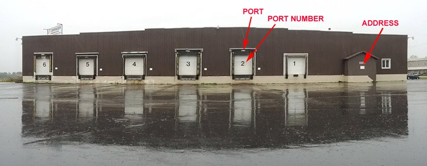
Visiting our warehouse service a couple of weeks ago, I was struck by the analogy possible between the idea of computer ports and a multi-tenant warehouse, so whipped out my Android smartphone and took a picture with the totally cool panoramic feature.
The warehouse is analogous to the host computer. It has a single street address. It handles goods for multiple users. Users have space allocated inside the warehouse. The warehouse has (on this side) six ports, also called loading docks. Each port has a number. A user can be assigned a port, either temporarily or permanently.
To communicate goods to that user, they’re carried in a shipping container (IP packet) on a truck (Ethernet frame) over a road (LAN cable) to the warehouse at its street address (IP address). To get the contents of the shipping container delivered to the correct user, the truck is backed up to the appropriate loading dock (port) identified by its door number (port number) and the contents of the container are unloaded to the space behind that port.
In computer communications today, the port number is 16 bits long, and the source and destination port number are populated at the beginning of the transport layer header, Layer 4 of the OSI model. The world’s most popular standard protocols for implementing the transport layer are the TCP (Transmission Control Protocol) and UDP (User Datagram Protocol).
Hence, one hears of “TCP ports” and “UDP ports”, particularly when configuring rules for packet forwarding on a router or firewall. When one “blocks” a port, that means that communication to a particular computer program is denied. When one “opens” a port, communication to that computer program is being allowed.
Standard practice is to allow communications only to specifically-identified ports and deny all other communications.
The port number of the application and the IP address of the host computer concatenated together is called a socket in UNIX and IP and is called a transport service in the OSI model. The result is the ability to identify the specific source computer program on one computer and the specific desired destination computer program on a different computer.
The Internet connection at your office dies. Lights on your modem are flashing in a strange pattern. You call the ISP, and they quickly diagnose that the modem power supply has failed, and they will overnight you a replacement. Presumably you are not the first person to have this problem with that modem.
So how do you continue to operate while you are waiting for the replacement power supply? It’s hard to run your business without e-mail and ordering and administration systems, which are all accessed via the Internet.
If you want availability, you need two connections to the Internet, so if one fails you are not out of business. We go over this in the lesson “Mature Competitive Carrier Network: Regional Rings, POPs and MANs”, slide 3.17 of Course 101, Telecom Datacom and Networking for Non-Engineering Professionals, and mention it in pretty much every other course.
A large business will be a station on a Metropolitan Area Network, which is a ring, meaning two connections to the Internet for that business and automatic reconfiguration in the case of one failing. But this is expensive… the second connection is not free.
Small and medium businesses usually have a single DSL or cable modem connection to the Internet. When that fails, connectivity to email, ordering and administration servers is impossible, and many businesses these days would be “dead in the water” until the ISP fixes the problem with their hardware.
Unless you have an Android smartphone, a good “data” plan and a laptop with WiFi running Windows.
The scenario described happened at our office last week. Since many of our customers might find themselves in a similar situation – even at home – I thought I’d share the quick and painless solution I came up with. Even if you’re not likely to need this solution, understanding how it works will no doubt sharpen your understanding of the devices involved and their functions.
In this tutorial, I will use the technology in our office: 16 Mb/s DSL, Android smartphone and Windows laptop. The solution is equally applicable to an Internet connection using a cable modem or if you are one of the lucky few, an Internet connection via fiber.
For the smartphone and laptop, there may be equivalent functions on Apple products, but as I am allergic to Apples, we don’t have any in the office. I’m posting this tutorial on our Facebook page, our Google+ page, or our blog; I invite someone better able to tolerate Apple products to leave a comment whether and how the iPhone and MacBook can perform the required functions.
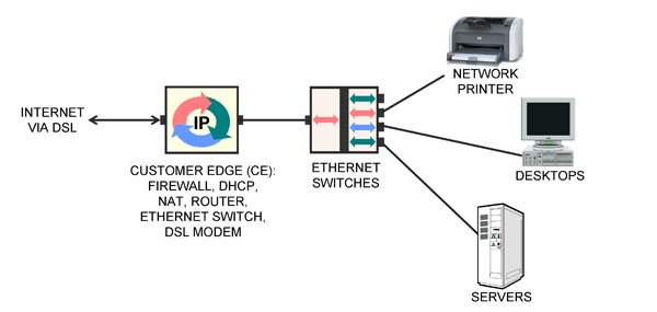
Figure 1: Normal network setup
Figure 1 illustrates the normal network setup in our office, a typical configuration for networking at a small or medium business. On the left is the access circuit to the Internet Service Provider (ISP), terminating on a modem in our office.
The modem is contained in a box that also includes a computer and an Ethernet switch. This box is more properly called the Customer Edge (CE).
The computer in the CE runs many different computer programs performing various functions: Stateful Packet Inspection firewall, DHCP server offering private IP addresses to the computers in-building, DHCP client obtaining a public IP address from the ISP, a Network Address Translation function between the two, routing, port forwarding and more.
In-building is a collection of desktop computers, servers and network printers. These are connected with Category 5e LAN cables to Gigabit Ethernet LAN switches, one of which is also connected to the CE.
When a desktop computer is restarted, its DHCP client obtains a private IP address and Domain Name Server (DNS) address from the DHCP server in the CE. The private address of the CE is configured as the “default gateway” for the desktop by Windows.
When a desktop computer wants to communicate with a server over the Internet, it looks up the server’s numeric IP address via the DNS, then creates a packet from the desktop to the Internet server and transmits it to its default gateway, the CE.
The NAT function in the CE changes the addresses on the packet to be from the CE to the Internet server and forwards the packet to the ISP via the modem and access circuit. The response from the Internet server is relayed to the CE, where the NAT changes the destination address on the return packet to be the desktop’s private address and relays it to the desktop.
The solution for restoring Internet access after the CE died is illustrated below.
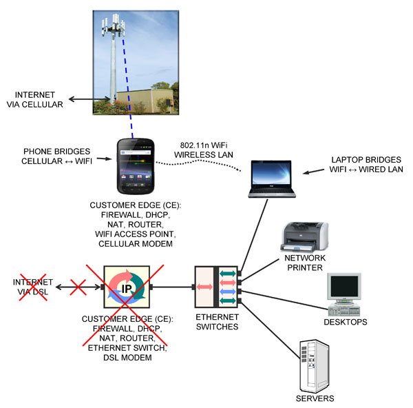
Figure 2 Restored Internet Access via Cellular
An Android smartphone and a laptop running Windows were used to restore connectivity to the Internet without making any changes to the desktops, servers or network printers.
First, I took my Samsung/Google Nexus smartphone running Android out of my pocket and plugged in the charger.
Then on its menu under Settings > more > Tethering & portable hotspot > Set up Wi-Fi hotspot, I entered a Network SSID (“TERACOM”) and a password, clicked Save, then clicked Portable Wi-Fi hotspot to turn it on.
The smartphone is now acting as a wireless LAN Access Point, just like any other WiFi AP at Starbucks, in the airport or in your home.
At this point, the smartphone is the CE device, performing all of the same functions that the DSL CE device had been before it died: firewall, DHCP client to get a public IP address from the ISP (now via cellular), DHCP server to assign private IP addresses to any clients that wanted to connect (now via WiFi), NAT to translate between the two and router to forward packets.
Just as the DSL CE equipment “bridged” or connected the DSL modem on the ISP side to the Ethernet LAN in-building, allowing all the devices on the LAN to send and receive packets to/from the Internet via DSL, the smartphone “bridges” or connects the cellular modem on the ISP side to the WiFi wireless Ethernet LAN in-building, allowing all the devices on the wireless LAN to send and receive packets to/from the Internet via cellular radio.
The remaining problem was that none of the desktops or servers had wireless LAN cards in them, so they could not connect to the smartphone AP and hence the smartphone’s cellular Internet connection.
What was needed was a device to “bridge” or connect the wired LAN to the wireless LAN in-building. By definition, this device would need two LAN interfaces: a physical Ethernet jack to plug into the wired LAN, plus a wireless LAN capability.
Looking around the office, I spotted two devices that fit this description. One of them was my laptop, with both a LAN jack and wireless LAN.
I fired up the laptop, plugged it into an Ethernet switch with a LAN cable, and in the Network and Sharing Center, clicked Change Adapter Settings to get to the Network Connections screen that showed the two LAN interfaces.
I enabled both the wired and wireless LAN interfaces. Then right-clicking the Wireless Network Connection icon, selected the TERACOM wireless network and entered the password.
Once that was successfully connected, I selected the two adapters in the Network Connections screen, right-clicked and chose “Bridge Connections”. A message saying “Please wait while Windows bridges the connections” appeared, then an icon called “Network Bridge” appeared, and after a few seconds, “TERACOM” appeared as well.
My laptop was now acting as an Ethernet switch, connecting the wired LAN to the smartphone’s wireless LAN.
Each of the desktops, servers and network printers in the office had to be rebooted so they would run their DHCP client again, obtaining a private IP address and DNS address from the smartphone AP, and be configured so the smartphone was the “default gateway” in Windows.
After rebooting my desktop computer, it had Internet access over the wired LAN, through the wired Ethernet switch to my laptop, to the smartphone via WiFi then to the ISP over cellular.
After rebooting the other desktops and servers, all had Internet access again, with no changes to the configuration of the desktops or servers.
This took about 20 minutes to get up and running, and we were back in business. Running a bandwidth test on speedtest.net, I found we had exactly 5 Mb/s connection to the Internet via cellular.
Obviously my cellular service provider limited the connection to 5 Mb/s in software – but who’s complaining? 5 Mb/s is more than three times as fast as a T1, which cost $20,000 per month when I first started in this business 20 years ago.
I hope you found this tutorial useful, either as a template for your own emergency backup Internet connection, or simply as a way of better understanding the devices, their functions and relationships.– EC
Note 1: You must verify your billing plan for “data” on your cellular contract before doing this. I have 6 GB included, which means basically unlimited, and that includes the WiFi hotspot traffic. Make sure you have something similar, to avoid receiving a bill for $10,000 for casual “data” usage.
Note 2: As always, this tutorial is provided as general background information only. We do not guarantee it will work for you. Each situation is unique and requires professional advice to identify and resolve issues including but not limited to performance and security. This tutorial is not professional advice. But I hope you have found it valuable.
Note 3: I might have been able to implement this without the laptop. If you’d like to know that, or what was the other device I could have used to bridge the wired and wireless LAN in-building, or suggest how this could be done with Apple products, please leave a comment.
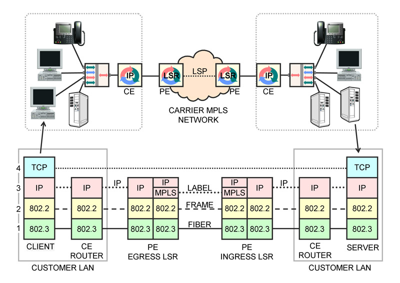
We’re getting ready to release another Online Course at the end of March: L2014 “MPLS and Carrier Packet Services.”
As a sneak preview, this newsletter’s free tutorial is part of Lesson 11 “TCP/IP over MPLS” from that course.
NOTE: You may find this tutorial a bit overwhelming, landing smack on your computer screen with no preparation, like a parachutist whose chute didn’t open landing in a cow field.
In the Online Course “MPLS and Carrier Packet Services”, there are TEN lessons building up to this one.
The tutorial is part of the text and one graphic from Lesson 11 “TCP/IP over MPLS”. The Online Course when released at the end of March will have extensive animations following along with a voiceover of the text. Enjoy!
The popular press and news feeds have been full of stories about advocates of “net neutrality” testifying to congressional committees, lobbying the federal government and railing against the big ISPs over the past while. Not much mention of arguments against net neutrality, though. It’s hard to decide whether those arguing for net neutrality are foolish, ignorant or disingenuous.
Let’s begin with some definitions. When someone demands “net neutrality”, they usually mean that the network must not discriminate between applications being carried in IP packets; that identical transmission characteristics (throughput, delay, number of errors, etc.) are to be provided for all packets regardless of what is being carried in them. They claim (correctly) that this is not the case at present, that the network service provider is “throttling” certain applications, “slowing down” or “shaping” traffic and that this, in their opinion, must stop. They sound the rallying cry “the net should be free”.
What a load of hogwash.
But are these arguments foolish, ignorant or disingenuous? Hard to decide: