Lesson 9 from the new release of Course 2206 Wireless Telecommunications
Telecommunications Training Blog
Tutorials and articles from Teracom Training Institute. Bringing you the best in telecom training and certification since 1992.
The full lesson free, in full quality, with our compliments.
Lesson 9 from the new release of Course 2206 Wireless Telecommunications

From the new textbook Telecom 101 Fifth Edition: 2020

Figure 111. SFP Optical Transceivers
10.5 Optical Ethernet
Optical Ethernet is signaling MAC frames (Section 4.4) from one device to another by flashing a light on and off; light on represents a 1 and light off represents a 0 in many systems.
The light, called a wavelength or lamda – λ in Greek – is as close to one single pure frequency as possible, in the infra-red, lower frequencies than what our eyes detect.
In sophisticated systems, the wavelength might be modulated with QAM (Section 3.4) to increase the bit rate.
Normally, Optical Ethernet is implemented as point-to-point connections: from a hardware port on one switch or router to a hardware port on another switch or router in a different building. This includes connections between core routers in cities, connections between routers and switches within a city, and connections from carriers to customers.
10.5.1 SFP Modules and Connectors
The light is generated by a laser controlled by pulses of electricity at the transmitter. The intensity and sometimes phase of the light is modulated, i.e. changed in discrete steps, to represent bits optically based on the pulses of electricity. Up to 80 km (50 miles) away at the other end of a tube of glass thinner than one of your hairs, a photodetector at the receiver measures the received light and decides what bits are being represented, and transmits them onward as pulses of electricity.
As illustrated in Figure 111, most systems use two fibers, one for each direction. A device combining the transmitter and detector functions is called an optical transceiver.
This device has metal connectors on one side to plug into a slot on a router or switch, and optical connectors on the other side, either factory- or field-installed on the fibers plugged into the transceiver.
These transceivers are typically implemented as Small Form-factor Pluggable (SFP) modules, which are hot-swappable in the terminating equipment at each end.
100 Gb/s being communicated through this transceiver is the high end of commercially-deployed technology in 2020.
In some cases, the SFP modules are embedded in the terminating equipment, meaning the fibers are plugged into the terminating equipment. This allows re-use of existing fiber. In other cases, the SFP modules are attached to fiber cables by the fiber cable manufacturer, meaning the SFP module is plugged into the terminating equipment. This ensures the fiber and transceiver technology are matched and the optical connection is a high-quality “factory” connection.
The SFP module format is not the subject of a standard, but rather described in industry Multiple Sourcing Agreements (MSA).
10.5.3 IEEE Standards
There are many technologies for transceivers implemented in the SFP module. Some are proprietary; many are standardized by the IEEE. In practice, the same manufacturer’s product is used at both ends of the fiber to ensure compatibility. The table in Figure 112 lists current IEEE standards. More will be published in the future.
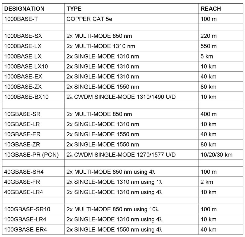
Figure 112. IEEE Optical Ethernet Standards
Most technologies use one fiber for each direction. Some, like for fiber to the home, use two wavelengths for two directions on one fiber. The bitrate of the standards beginning with 1000 is 1,000 Mb/s, or 1 Gb/s. A G at the beginning means Gigabits/second. 40 and 100 Gb/s technologies split the bitstream into subrates and transmit them in parallel on different wavelengths called paths or lanes.
The reach is the maximum length of fiber between devices. Single-mode and multimode are designations for different qualities of fiber. Most if not all builds today use single-mode fiber.
Source: Telecom 101 textbook / reference book, Fifth Edition: 2020 available in print and eBook.
Now that 4G cellular mobile is settled, talk is now turning to 5G.
The first thing to know about 5G is that there are currently no standards, no detailed agreement on what exactly it will be. But we have a number of general indicators to guide the discussion:
1. 5G will employ radio frequencies well above what is currently used for cellular.
The current frequency bands for 3G/4G cellular top out at about 2.6 GHz. Proposals for frequency bands for 5G include “millimeter wave” bands, that is, wavelengths varying between 1 and 10 mm, which correspond to frequencies between about 30 and 300 GHz. No doubt, in the future, there will be unified 5G systems with variations operating in all frequency bands; but the current emphasis is on new technology in the millimeter wave bands.
2. 5G will provide very high bit rates.
With carrier frequencies at 30 GHz and above, very wide frequency bands around those center frequencies can be employed, allowing the radio frequency modems to achieve high numbers of bits per second. In addition, Multiple-Input, Multiple-Output (MIMO) designs can implement massive parallel communications, radically increasing the capacity available to a user. Initial designs and trials have measured 5 Gb/s (5,000 Mb/s). No doubt, this will be pushed beyond 10 Gb/s.
3. Initially, 5G will not be a replacement for 4G.
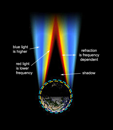
At millimeter wave frequencies, in-building penetration and refraction around obstacles is poor, and the atmosphere attenuates (diminishes) the signal to the point that line-of-sight between the antennas is necessary, and useful transmission range is measured in the hundreds of meters (yards). This means that the first deployments of 5G will be in environments where base stations can be closely spaced.
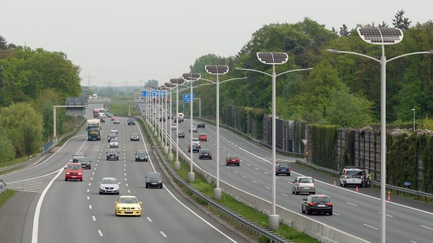
One application for all this bandwidth is traffic control: going beyond today’s standalone self-driving vehicles to vehicles communicating with each other and with traffic control systems, with base stations deployed on street lights as suggested by the picture.
Like many, many other pieces of jargon in the business, many people would like to understand just what exactly it is.
SIP is an acronym for Session Initiation Protocol. This is a standards-based method of setting up Voice over IP telephone calls.
A key thing to know about Voice over IP phone calls is that once the call is set up and two people are talking, their telephones exchange IP packets with digitized speech in them directly.
One person’s telephone creates an IP packet and puts the IP address of the other person’s telephone in the destination address field. This packet is forwarded by routers directly to the other person’s phone.
To be able to do this, it is necessary to know what the other person’s IP address is!
This is the main function performed by SIP: it is an assistant to enable a caller to find out the IP address of the called party’s telephone, so they can send packets with digitized speech to that person’s phone.
Trunking is a term that has been generally used in the telecom business in the past to mean communication between telephone switches. Trunks connect CO switches, toll centers and other switches in the PSTN.
PBX trunks connect an organization’s private switch to a CO switch.
SIP Trunking is a term invented by the marketing department to mean to mean “native communication of SIP call setup messages and Voice over IP traffic between an organization’s locations, with a Service Level Agreement and transmission characteristics sufficient to guarantee the sound quality.” And a gateway service thrown in.
Native means carrying the IP packets without converting them to an old-fashioned telephone call. The IP packets in question are at first carrying SIP call setup messages, then once the call is set up, the IP packets each contain typically 20 ms of digitized speech.
SIP Trunking replaces the previous architecture of PBX trunks.
It would be more accurate to refer to this new service as “SIP and Voice over IP Trunking” – but “SIP Trunking” rolls off the tongue better…
To learn more, attend BOOT CAMP March 27-31, or just the last two days of BOOT CAMP, which are Course 130 Understanding Voice over IP March 30-31.
New video posted! This is part of the introductory lesson of CTNS Course 2206 Wireless Telecommunications.
For more information:
Course page: https://www.teracomtraining.com/online-courses-certification/teracom-overview-l2106.htm
CTNS Certification page:
https://www.teracomtraining.com/online-courses-certification/teracom-overview-ctns.htm
Wireless Telecommunications is a comprehensive course on wireless, mobile telecommunications plus wireless LANs and satellites.
We begin with basic concepts and terminology including base stations and transceivers, mobile switches and backhaul, handoffs, cellular radio concepts and digital radio concepts.
Then, we cover spectrum-sharing technologies and their variations in chronological order: GSM/TDMA vs. CDMA for second generation, 1X vs. UMTS CDMA for third generation along with their data-optimized 1XEV-DO and HSPA, how Steve Jobs ended the standards wars with the iPhone and explaining the OFDM spectrum-sharing method of LTE for 4G.
This course is completed with a lesson on WiFi, or more precisely, 802.11 wireless LANs, and a lesson on satellite communications.
You’ll gain a solid understanding of the key principles of wireless and mobile networks:
• Coverage, capacity and mobility
• Why cellular radio systems are used
• Mobile network components and operation
• Registration and handoffs
• Digital radio
• “Data” over cellular: Internet access
• Cellular technologies: FDMA, TDMA, CDMA, OFDM
• Generations: 1G, 2G, 3G, 4G
• Systems: GSM, UMTS, 1X, HSPA, LTE
• WiFi, 802.11 wireless LANs
• Satellite communications
Here’s Lesson 1 from our new Course 2221
Fundamentals of Voice over IP. Cheers!
It is important to understand how packets and frames are related, and in particular, IP packets vs. Ethernet or MAC frames.
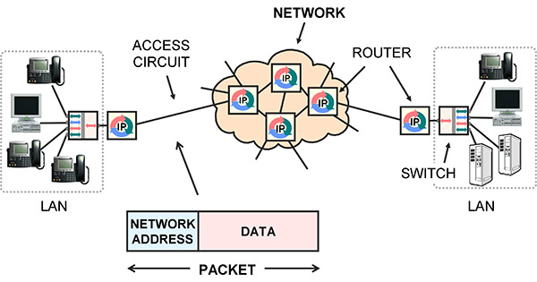
Packets are for networks. A packet is a block of user data, such as a piece of an e-mail message, with a network address on the front. The network address is the final destination. The standard for network addresses is IP.
Network equipment like routers receive an IP packet on an incoming circuit, examine the indicated destination IP address, use it to make a route decision, then implement the decision by forwarding the packet to the next router, on a different circuit.
A frame is a lower-level idea. Frames are used to communicate between stations on the same circuit. The circuit may have multiple stations physically connected onto it, like a wireless LAN, a few stations connected by a LAN switch, or only two stations like a point-to-point LAN cable. Each station has a Media Access Control (MAC) address, sometimes called a hardware address, link address or Layer 2 address.
A frame has framing to mark the beginning and end, sender and receiver MAC addresses to indicate the stations on the circuit, control information, a payload and an error detection mechanism.
The frame is transmitted on the circuit, and all stations on the circuit receive it. If an error is detected at a receiving station, the frame is discarded and might have to be retransmitted somehow.
If no errors are detected, the receiver compares the destination MAC address on the received frame to its own MAC address, and if they are the same, processes the frame, extracting the data payload and passing it to higher level software on the receiver.
If the MAC addresses are not the same, the receiver ignores it and waits for the next one.
The end result is that the payload in the frame is communicated to the correct station on the same circuit, with no errors.

The main purpose of packets is to append an IP address to your data. The IP address is used by network equipment to make route decisions: to relay the packet from one circuit to a different circuit. This is accomplished by receiving the packet then transmitting it to a different machine, usually the next router in the chain.
To actually transmit a packet to another router, the packet is inserted as the payload in a frame, then the frame is broadcast on the circuit that connects to the next router.
Notice that there are two addresses: the IP network address and the MAC address.
The IP address on the packet is the final destination, and so does not change. The MAC address on the frame indicates the destination on the current circuit, and so is changed as the data is forwarded from one circuit to another.
This and related topics are covered in:
• Instructor-Led Course 101
Telecom, Datacom and Networking for Non-Engineering Professionals
This is Section 2.9.1 of the new Telecom 101, 4th edition
print and ebook available January 2016
.
Brought to you by BOOT CAMP
January 25-29 2016 – Silicon Valley
– – –
This diagram provides a very high-level block diagram view of the processes involved in communicating speech in IP packets from one person to another:

Starting on the left, commands from the speaker’s brain cause combinations of lungs, diaphragm, vocal cords, tongue, jaw and lips to form sounds.
A microphone is positioned in front of the mouth and acts as a transducer, creating a fluctuating voltage which is an analog or representation of the sound pressure waves coming out of the speaker’s throat.
This is fed into a codec, which digitizes the voltage analog by taking samples of it 8,000 times per second and coding the value of sample into binary 1s and 0s. Typically, the value of each sample is represented with a byte, meaning 64 kb/s to be transmitted.
Approximately 20 ms worth of coded speech is taken as a segment and placed or encapsulated in an IP packet.
The IP packet begins with a header, which is control information, the most interesting part being the IP address of the source telephone and IP address of the destination telephone.
IP packets are moved from the source to the destination over a sequence of links.
The links are connected with routers, which relay the packets from one link to the next.
Lower level functions such as framing and link addressing are usually performed following the IEEE Ethernet and MAC standards.
At the lowest level, the links are physcially implemented with Category 6 LAN cables, DSL modems, Cable modems, fiber optics and radio systems.
At the destination, the bits are extracted from the IP packet and fed into a codec, which re-creates the analog voltage.
This voltage drives a speaker, which re-creates the sound pressure waves, which travel down the ear canal to the inner ear, causing hairs on the cochlea to vibrate, triggering neural impulses to the brain, making the listener think they are hearing something.
– – –
It’s important to note that the voice packets are communicated directly from one telephone to the other over the IP network.
The packets do not pass through a CO telephone switch, for example.
– – –
For a full explanation of all of the technologies mentioned in this tutorial, register for BOOT CAMP in Sunny Silicon Valley in January!
BOOT CAMP
is Core Training Course 101 Telecom, Datacom and Networking for Non-Engineering Professionals
and VoIP Course 130 Understanding Voice over IP
in one week at a discounted price.
Get this career-enhancing boost. Check it out!
Telecommunications technology is constantly changing and improving – seemingly faster and faster every year – and at Teracom, we keep our training courses up to date to reflect these changes. In a previous post, we identified eight major developments and trends in telecommunications incorporated in our training.
In this post, we take a closer look at the fourth development:
a worldwide standard for mobile wireless has finally been achieved with 4G LTE.
Mobility means it is possible to start communicating with a particular radio base station, then when moving physically away, be handed off to another base station down the road to continue communications uninterrupted. In a non-mobile system (like WiFi), communication ceases if you move too far away.
The first generation (1G) of mobile radio was characterized by analog FM on frequency channels. Numerous incompatible systems were deployed: AMPS in North America, TACS in the UK, NMT in Finland and others.
The second generation (2G) was digital, which means modems communicating 1s and 0s between the handset and base station. Again, several incompatible systems were deployed, and two warring factions emerged, which could be called the “GSM/TDMA faction”, and the “CDMA faction”.
By far, the most popular 2G system was GSM, a European technology where a number of users time-share a single radio channel. Another system was IS-136, called “TDMA” in North America, deployed by the company currently known as AT&T Wireless in the US and Rogers in Canada.
A less popular 2G system employed CDMA, using technology patented by American company Qualcomm, and deployed by Verizon, Sprint and Canadian telephone companies.
These 2G systems were totally incompatible. A basic phone from a carrier could not work on another carrier unless they both used exactly the same system.
To try to avoid a repeat of the incompatibility for the third generation, the International Telecommunications Union (ITU) struck a standards committee in year 2000 called IMT-2000, its mission to define a world standard for 3G.
They failed. IMT-2000 instead published a 3G “standard” with five incompatible variations. The two serious variations were both CDMA – but differed on the width of the radio bands, the control infrastructure and synchronization method among other things.
The GSM/TDMA faction favored the deployment of CDMA in a 5 MHz wide band. This was called IMT-DS, Direct Spread, Wideband CDMA and Universal Mobile Telephone Service (UMTS). Its data-optimized version was called HSPA.
The CDMA faction favored a strategy that was a basically a software upgrade from 2G, employing existing 1.25 MHz radio carriers. This is called IMT-MC, CDMA multi-carrier, CDMA2000 and 1X. Its data-optimized version was called 1XEV-DO.
Again, these 3G systems were completely incompatible. A basic UMTS phone could not work on a 1X network.
Market forces finally pushed the two camps together.
The fact that there were far more users in the GSM/TDMA faction meant that their phones were less expensive, had better features and appeared on the market first. This put the carriers in the CDMA/1X faction at a disadvantage. This trend was continuing into 3G, where UMTS phones would have the same advantage over 1X phones.
Then, Steve Jobs invented the world’s most popular consumer electronic product, the iPhone – but only permitted carriers in the GSM/TDMA/UMTS faction to have it. This severely tilted the playing field.
In the face of this, the CDMA/1X faction threw in the towel, and decided to go with the GSM/TDMA/UMTS faction’s proposal for the fourth generation (4G), called LTE, to level the playing field.
And once this was agreed, Steve Jobs allowed the iPhone on all networks. One of the legacies of Steve Jobs will not just be the iPhone, but ending the standards wars by pushing the industry to agree on LTE as a single worldwide standard for mobile communications as of the fourth generation, using the leverage of his iPhone.
I hope you’ve found this article useful!
If you like, you can watch a video segment of our instructor explaining why LTE became a worldwide standard on youTube
Additional explanation of cellular concepts, TDMA, CDMA and LTE is available in:
– Teracom online tutorials
– Course 101: Telecom, Datacom and Networking
for Non-Engineering Professionals
– Textbook T4210 Telecom, Datacom and Networking
for Non-Engineers
– Online Course 2206 Wireless Telecommunications
(part of the CTNS certification coursework)
– Online Course 2232 Mobile Communications
(part of the CWA certification coursework), and
– DVD Course V6 “Wireless”
This tutorial on Bluetooth is Lesson 2: Bluetooth, from Course 2233 “Fixed Wireless”. Watch the lesson by clicking the picture below.
You can also watch the video on YouTube.
The text is from the Course book / CWA certification study guide.
Enjoy!

Click the image to watch the full lesson. The text that follows is from the course book.
Bluetooth is a set of standards for short-range digital radio communication published by a consortium of companies called the Special Interest Group. It was originally developed as a wireless link to replace cables connecting computers and communications equipment.
Bluetooth connections are called piconets and Personal Area Networks since (in theory) up to eight devices can communicate on a channel within a range of 1 to 100 meters depending on the power.
In reality, Bluetooth is mostly used point-to-point with ten meters range.
The first data rate for Bluetooth was 0.7 Mb/s, followed by an enhancement to “3” Mb/s (2.1 Mb/s in practice). A High Speed variation employs collocated Wi-Fi for short high-bitrate transmissions at 24 Mb/s. The Smart or Low Energy variation allows coin-sized batteries on devices like heart-rate monitors.
Applications include wireless keyboard, mouse and modem connections… though today, 2 Mb/s Bluetooth is likely slower than the modem.
Bluetooth is used to replace wires connecting a phone to an earpiece, or to an automobile sound system for hands-free phone calls while driving. In this case, both two-way audio and two-way control messages are transmitted.
Bluetooth is also used to stream music from a smartphone to a receiver connected to an amplifier and speakers in an automobile or in a living room.
In the future, wireless collection of readings from devices like heart-rate monitors will be widespread.
Each of these types of applications corresponds to a Bluetooth profile, which is a specified set of capabilities and protocols the devices must support.
Bluetooth implements frequency-hopping, where the devices communicate at one of 79 carriers spaced at 1 MHz in the 2.4 GHz unlicensed band for 625 microseconds (µs), then hop to a different carrier for 625 µs, then to another, in a repeating pattern known to both devices. A particular hop sequence is called a channel, and is identified by an access code.
This is called Frequency-Hopping Spread Spectrum (FHSS), since hopping between 79 carriers spreads energy across spectrum 79 times wider than one carrier. It has the advantage of reduced sensitivity to noise or fading at any particular carrier.
If different pairs of devices are using different hop sequences, they can communicate at the same time in the same place without interfering. There are security advantages if the hop sequence can not be determined by a third party.
The initiator of communications is called the master. It determines the frequency hopping pattern, when the pattern begins, when a packet begins and when a bit begins. The packet and bit timing is based on the master’s clock, which ticks every 312.5 microseconds. Two ticks make a slot. A slot corresponds to a hop. The master transmits and the slave listens in even-numbered slots; vice-versa in odd-numbered slots.
To establish the channel, the master derives a channel access code from its Bluetooth address, and indicates the code to the slave at the beginning of every packet. Both master and slave use this to determine the actual frequency-hopping sequence.
Data is organized into Bluetooth packets for transmission. Packets can be 1, 3 or 5 slots long. A bit rate of 2 Mb/s would mean Bluetooth packets are about 150, 450 or 750 bytes long.
Discovering other devices means sending requests in packets on pre-defined channels called inquiry scan channels. Making a device discoverable means it listens on the inquiry channels, and responds to inquiries with information like its Bluetooth address, name and capabilities. This results in a list of Bluetooth devices displayed on the discovering device, such as a smartphone.
Connecting to a device means paging the device on its paging channel, a channel with access code derived from the target’s Bluetooth address. Devices listen on their paging channel, and respond to pages to establish a session. Once the session setup protocol is completed on the paging channel, the devices begin communicating on the channel defined by the master.
The frequency hopping pattern can be adapted to skip carriers where the signal to noise ratio is permanently low, to improve overall performance.
I hope you’ve enjoyed this tutorial!
This discussion is covered in the following Teracom training courses:
• DVD-Video Course V6: Understanding Wireless
https://www.teracomtraining.com/video_courses.htm
• Online Course 2233 Fixed Wireless
https://www.teracomtraining.com/online-courses-certification/certified-wireless-analyst-cwa.htm#2233